I think 2SC2922/2SA1216 are "ring emitter" epitaxials .
Higher Hfe/Ft/SOA.
These are cool devices ! , easily run 3 pair with a 1A driver pair 🙂 .
Too bad most are "fakes". 🙁
OS
Higher Hfe/Ft/SOA.
These are cool devices ! , easily run 3 pair with a 1A driver pair 🙂 .
Too bad most are "fakes". 🙁
OS
Hi Damir,
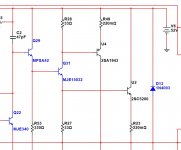
Attached is schematic with the values I used for simulation presented earlier.
In Multisim it shows no problem with stability.
You're right about the mistake in initial schematic - result of manual transfer from Multisim to Diptrace. So it is copied on the PCB 🙁( Thanks for pointing it out.
If the specified compensation values don't improve the situation, you can try increasing NFB network values (R6/R9) proportionally - higher values will provide a bit higher distortion, but also higher stability margin. The ones I use push it close to the limit. It will be interesting to see where you end up in your simulation.
I will try to move to LTSpice - from what I see, it allows more flexibility, but look like less convenient in terms of user interface (probably I'm just not familiar with it as yet).
BTW, if somebody has got SPICE models for Sanken transistors (2SC4382/2SA1668, 2SC2922/2SA1216) - they would be very much appreciated. I use them in live prototypes, but have to substitute them in simulation. Previous prototypes showed such substitution works good enough, however having original models (or at least better ones) would be great.
Best regards,
Valery
I have 2 of these amps already out there ....
- R6 / R9 ?? that's a lot of current there , almost 1/4A on the 11R !
- Just a little degeneration on the input buffer. 22R won't "slow it
down" much.
In fact , for "real fast" ....22R Q1/2 - Q7/8 Re's all around R9=22 and R6=560-680.
Better offset and stability.
What happened to those VAS shunt resistors ?
All the luxman hawksford's use them. Values of 47-100K.
VAS Z will change greatly
with frequency. I found that I could use lower value caps (15-22p),
with even 100-150K shunt resistors in parallel with the caps.
OS
I see a lot of SIM variations explored here - most with excellent performance. One thing is missing in the data -- OPS idle current (bias).
Some literature seems to indicate 60-80 mA for BJT OPS is about right. Other places much less.
So, I just did a test tonight here on a VFA of 250W/8. I used a THD analyzer to set the OPS bias for lowest THD. The best results are around 26 mA per OP transistor (with 0.1 Ohm Re). 60-80mA produced high distortion levels.
I believe it was Bonsai who recently said 26mA would be best in a comment to my Marantz CFA power amp biasing.
Can I get some data of OPS idle bias for the various CFA SIM circuits?
THx-RNMarsh
Last edited:
I see a lot of SIM variations explored here - most with excellent performance. One thing is missing in the data -- OPS idle current (bias).
Some literature seems to indicate 60-80 mA for BJT OPS is about right. Other places much less.
So, I just did a test tonight here on a VFA of 250W/8. I used a THD analyzer to set the OPS bias for lowest THD. The best results are around 26 mA per OP transistor (with 0.1 Ohm Re). 60-80mA produced high distortion levels.
I believe it was Bonsai who recently said 26mA would be best in a comment to my Marantz CFA power amp biasing.
Can I get some data of OPS idle bias for the various CFA SIM circuits?
THx-RNMarsh
Richard, I use 60-70 mA OPS quiescent current in both simulations and live prototypes. Practical THD measurements showed optimal performance within this range (Sanken transistors mentioned above)...
Attachments

I see a lot of SIM variations explored here - most with excellent performance. One thing is missing in the data -- OPS idle current (bias).
Some literature seems to indicate 60-80 mA for BJT OPS is about right. Other places much less.
So, I just did a test tonight here on a VFA of 250W/8. I used a THD analyzer to set the OPS bias for lowest THD. The best results are around 26 mA per OP transistor (with 0.1 Ohm Re). 60-80mA produced high distortion levels.
I believe it was Bonsai who recently said 26mA would be best in a comment to my Marantz CFA power amp biasing.
Can I get some data of OPS idle bias for the various CFA SIM circuits?
THx-RNMarsh
There were a lot of discussions about output stage quiescent current here in this forum. D. Self in his book shows that not the quiescent current is what is important but Vbe, so optimal quiescent current depends of output configuration and output transistor emitter resistor. For EF it's higher then for CFP.
Damir
Does this apply to a regular emitter-follower OPS? Wondering why the measured optimum with emitter-follower is lower than most use here. Higher Re makes optimum Ic higher?
[ I have read the D.Self part on bias re Vbe.... doesn't help]
Anyway, in your SIMs pls include what OPS idle current is being used for the THD/harmonic distortion being shown. The optimum appears to be in a very narrow/small range .. at least on this amp tested.
Thx-RNMarsh
[ I have read the D.Self part on bias re Vbe.... doesn't help]
Anyway, in your SIMs pls include what OPS idle current is being used for the THD/harmonic distortion being shown. The optimum appears to be in a very narrow/small range .. at least on this amp tested.
Thx-RNMarsh
Last edited:
Does this apply to regular emitter-follower OPS? Wondering why the measured optimum is lower than most use here.
[ I have read the D.Self part on bias re Vbe.... doesn't help]
Thx-RNMarsh
Simulation with LTspice supports Self. I don't have means to measure it in real amp.
Damir
because i see a narrow range for optimum bias (lowest) THD... I did some searching and came up with this:
www.bartk.us/t/tiki-index.php?page=emitter+follower+push+pull+biasing&structure=contents
emitter follower push-pull biasing- both in Vbe and Ic and THD.
I am in the narrow trough, i believe.
THx-RNMarsh
www.bartk.us/t/tiki-index.php?page=emitter+follower+push+pull+biasing&structure=contents
emitter follower push-pull biasing- both in Vbe and Ic and THD.
I am in the narrow trough, i believe.
THx-RNMarsh
Last edited:
Hi Damir,
Attached is schematic with the values I used for simulation presented earlier.
In Multisim it shows no problem with stability.
You're right about the mistake in initial schematic - result of manual transfer from Multisim to Diptrace. So it is copied on the PCB 🙁( Thanks for pointing it out.
If the specified compensation values don't improve the situation, you can try increasing NFB network values (R6/R9) proportionally - higher values will provide a bit higher distortion, but also higher stability margin. The ones I use push it close to the limit. It will be interesting to see where you end up in your simulation.
I will try to move to LTSpice - from what I see, it allows more flexibility, but look like less convenient in terms of user interface (probably I'm just not familiar with it as yet).
BTW, if somebody has got SPICE models for Sanken transistors (2SC4382/2SA1668, 2SC2922/2SA1216) - they would be very much appreciated. I use them in live prototypes, but have to substitute them in simulation. Previous prototypes showed such substitution works good enough, however having original models (or at least better ones) would be great.
Best regards,
Valery
Valery, I think that the main problem why I can't get your amp stable is CFP output stage.
I will try more but first what came to my mind is to change it to ordinary EF, maybe CFP is not suitable for the CFA. With CFP I need to add heavy shunt capacitive compensation and some RC on the drivers base to the ground, and still there are small glitches near the crossover points.
Damir
Mr. Marsh, what amp is this? Got a link to the schematic?So, I just did a test tonight here on a VFA of 250W/8. I used a THD analyzer to set the OPS bias for lowest THD. The best results are around 26 mA per OP transistor (with 0.1 Ohm Re). 60-80mA produced high distortion levels.
What power level, load & frequency did you do this bias test?
______________
Damir, most CFPs need some resistance on the input device emitter.
In #5844, that's Q16
Last edited:
Valery, I think that the main problem why I can't get your amp stable is CFP output stage.
I will try more but first what came to my mind is to change it to ordinary EF, maybe CFP is not suitable for the CFA. With CFP I need to add heavy shunt capacitive compensation and some RC on the drivers base to the ground, and still there are small glitches near the crossover points.
Damir
In my previous CFA I used simple Bryston-type OPS (attached) - works perfectly with 47pF at pre-drivers' bases (live). With 15-22pF there is a low-amplitude oscillation at 12.8MHz. In fact, CFP is a part of it. I also tested this setup with 2 transistors removed - showed no visible (and audible) change (except lower maximum power). Experiment EF would be also interesting, however in general I like the sound with Bryston or CFP better.
Damir, I very much appreciate your LTSpice tests - hope we reach stability in the prototype and end up with a good amp.
Cheers,
Valery
Attachments
I have 2 of these amps already out there ....
- R6 / R9 ?? that's a lot of current there , almost 1/4A on the 11R !
- Just a little degeneration on the input buffer. 22R won't "slow it
down" much.
In fact , for "real fast" ....22R Q1/2 - Q7/8 Re's all around R9=22 and R6=560-680.
Better offset and stability.
What happened to those VAS shunt resistors ?
All the luxman hawksford's use them. Values of 47-100K.
VAS Z will change greatly
with frequency. I found that I could use lower value caps (15-22p),
with even 100-150K shunt resistors in parallel with the caps.
OS
OS, thank you for the comments, I think some degeneration would make sense. 22 / 600 Ohm for NFB network also seem to be reasonable.
VAS shunt resistors - I think, I've got 47k ones there, or you mean something else?
Valery
I see a lot of SIM variations explored here - most with excellent performance. One thing is missing in the data -- OPS idle current (bias).
Some literature seems to indicate 60-80 mA for BJT OPS is about right. Other places much less.
So, I just did a test tonight here on a VFA of 250W/8. I used a THD analyzer to set the OPS bias for lowest THD. The best results are around 26 mA per OP transistor (with 0.1 Ohm Re). 60-80mA produced high distortion levels.
I believe it was Bonsai who recently said 26mA would be best in a comment to my Marantz CFA power amp biasing.
Can I get some data of OPS idle bias for the various CFA SIM circuits?
THx-RNMarsh
Richard,
the optimum bias current figure is 26mV/(Re+re') and drives from Barney Oliver's analysis from the 1970's. re' is the internal emitter resistance of the transistor, and includes the reflected base resistance.
If for a minute, we ignore re' and set the OPS Iq based on the above, we get 78mA for a 0.33 emitter degen resistance. This is what I usually do -I overbias the OPS a little bit because I prefer the sound. However, if I wanted do it accurately, I would have to include re'. What value base stopper resistor are you using?
This bias point using this method ensures the flatest gm curve for the output stage pair, hence lowest distortion.
BTW, self and Cordell cover this subject in their books.
Here is a link to the Barney Oliver article http://hifisonix.com/cross-over-distortion/ Heavy goiing, but worth the effort.
🙂
Last edited:
Gnome is really good , thimios built BOTH servo'ed editions with
VERY good tests.
This one (with vzaichenko's shunt) really goes to the "limit".
I saw his work - and took "a leap of faith".
I'm still trying to figure why? shunt comp. works so much
better with the VSSA/Hawksford combo.
Different proportions of the resistive shunt and the capacitive
will give either lower total THD or less (different) H5-7 ....
I'm still playing.
I did this combo before with other compensations and did not
even come close to single digit PPM- 700V/us slew.
OS
Ive said this long ago, and there were offcourse those that want to argue the issue, shunt compensation is ideal for CFA topology. Study and understand Sassens paper on shunt compensation and youll know the reasons why.
Ive said this long ago, and there were offcourse those that want to argue the issue, shunt compensation is ideal for CFA topology. Study and understand Sassens paper on shunt compensation and youll know the reasons why.
Do you have a link to this paper?
Not convinced that shunt compensation on its own is best. It seems a waste to do it this way when you can use miller compensation in conjunction with shunt compensation and linearize the VAS.
Do have an open mind though...
Do you have a link to this paper?
Not convinced that shunt compensation on its own is best. It seems a waste to do it this way when you can use miller compensation in conjunction with shunt compensation and linearize the VAS.
Do have an open mind though...
Mike B's VFA "symasym" does exactly that. Sets the main pole w/miller and
then uses shunt to "trim" the harmonics.
I have included BOTH miller and shunt (R/C) on the PCB for that amp
I previously posted.
It is said that this (shunt) is "VAS abuse" ... but I see it commonly
used by luxman and others (especially on the hawksford).
OS
Do you have a link to this paper?
Not convinced that shunt compensation on its own is best. It seems a waste to do it this way when you can use miller compensation in conjunction with shunt compensation and linearize the VAS.
Do have an open mind though...
Why would you want to combine the 2 ??
In CFA there is current on demand, shunt compensation does not affect the vas as in VFA topology. It allows for higher ULGF. This was already covered twice in this thread.
Also look closely at 2 pole compensation, youll notice it has more to do with shunt compensation than it does miller, thats why it works so well. 😉
I cant remember what the paper is called, I covered this 15+ years ago in varsity but google should be able to link the shunt compensation and Sassen.
Mike B's VFA "symasym" does exactly that. Sets the main pole w/miller and
then uses shunt to "trim" the harmonics.
I have included BOTH miller and shunt (R/C) on the PCB for that amp
I previously posted.
It is said that this (shunt) is "VAS abuse" ... but I see it commonly
used by luxman and others (especially on the hawksford).
OS
I havent studied the symasym, are you sure he didnt just implement 2 pole compensation ??
Who said it is vas abuse ?? It only is in the case of VFA (no current on demand) Actually it is very usefull in VFA if properly used for its intention. See D Selfs latest book, he has finally got it right.
It is said that this (shunt) is "VAS abuse" ... but I see it commonly
used by luxman and others (especially on the hawksford).
OS
Could always use a two pole shunt. Bootstrap it from the pre drivers. That reduces the load on the VAS at audio frequencies.
I'm interested in how shunt compensation interacts with the Hawksford VAS and why. The Hawksford cascode is something I would like to experiment with. It allows for VAS current limiting without using the classic approach. Potentially more efficient use of the extra transistor.
Why would you want to combine the 2 ??
In CFA there is current on demand, shunt compensation does not affect the vas as in VFA topology. It allows for higher ULGF. This was already covered twice in this thread.
I remember this being covered earlier as well.
Used both together in my prototypes as it works and is stable. But then I like to move the miller take off point to the pre drivers instead of VAS output.
Also look closely at 2 pole compensation, youll notice it has more to do with shunt compensation than it does miller, thats why it works so well. 😉
Fair point when using the VAS output as the take off point.
I cant remember what the paper is called, I covered this 15+ years ago in varsity but google should be able to link the shunt compensation and Sassen.
Have had a quick look but still at work. Don't think they'll see it as good use time. 😉
- Home
- Amplifiers
- Solid State
- CFA Topology Audio Amplifiers