____________________
Again, in case it isn't obvious, my aim is to equal or better da zillion device amps with much simpler topologies, NOT to accept a lower level of performance.
an engineer is someone who can do for 2 bob what any fool can do for a quid - Anon
Amen.
I propose that now is the time to start simplifying and the "Simplied" CFA topology is a good place to start doing that. I will put up one I did in awhile... if this is direction Bonsai and others want to go. The compli push-pull has also become a long time favorite for audio. Or we can continue this same CFA path but with bridged versions, etc. The classic topology IS the choice topology for high-end mfr/designs. Put up your hands.
Thx-RNMarsh
Last edited:
Over on the Slewmaster thread ostripper has shown a few different input sections and a universal output section that are based on known CFA topologies. One is a very simple design that I think is similar to Lazy Cats VSSA circuit with some changes, called the CFA-X V1.2 and another is based on a more evolved NAD circuit design. Perhaps we can bring those circuits into the discussion and that could be a start for you Richard?
Can we stop this semantic pedantic sh*t?
It serves NO useful purpose. It only reduces the S/N which makes it difficult to see the real gems among the BS.
This thread is about how to design amps without LTP i/ps which might be loosely called CFAs or even other topologies which might have some of their desirable characteristics.
Equally noisy and useless is posting performance figures without actual circuits that might help someone build a better amp.
If you want to wank, please start another thread titled "My d*ck is bigger than yours" or similar.
____________________
Welcome to the real world.
In case its not obvious, its MUCH simpler to ensure good layout, wiring, grounding etc with very simple circuits so 'real life' is close to SPICE world.
If you achieve 1ppm THD20k @full power with 2 x bc184s and a piece of wet string in SPICE world, you are FAR more likely to get single digit ppm in the practical device (assuming a reasonable level of competence) .. than with a zillion or even 56 devices .. even with zillion layer PCBs.
Again, in case it isn't obvious, my aim is to equal or better da zillion device amps with much simpler topologies, NOT to accept a lower level of performance.
an engineer is someone who can do for 2 bob what any fool can do for a quid - Anon
One correction in the above: I counted incorrectly, there are 58 transistors in the gain stages (60, if I count the integrated Darlingtons as 2 devices). I apologize for the misleading error.
Over on the Slewmaster thread ostripper has shown a few different input sections and a universal output section that are based on known CFA topologies. One is a very simple design that I think is similar to Lazy Cats VSSA circuit with some changes, called the CFA-X V1.2 and another is based on a more evolved NAD circuit design. Perhaps we can bring those circuits into the discussion and that could be a start for you Richard?
He did .. his 2 posted PDF's were representive of those two topologies.
As far as CFA/VFA ... the line has "blurred" for me.
My question is simple .... is the great performance/sound Q the result
of just the current Feedback ? , or is it just the fact that these amps are
balanced /symmetrical (true push-pull).
An augmented VFA "leach" actually has these CFA's beat in ALL aspects. 😛
(PSRR , slew , thd20 , LF thd) ... even clipping !
PS- the "CFA" trick is good to reduce parts count.
Last edited:
Amen.
I propose that now is the time to start simplifying and the "Simplied" CFA topology is a good place to start doing that. I will put up one I did in awhile... if this is direction Bonsai and others want to go. The compli push-pull has also become a long time favorite for audio. Or we can continue this same CFA path but with bridged versions, etc. The classic topology IS the choice topology for high-end mfr/designs. Put up your hands.
Thx-RNMarsh
YES , I am now looking to improve on my last design.
I added your CM's (as in your PDF) ,to my known working 2 stage
CFA. (the NAD/nx - below).
Adding Q11-14 brought very little to the table ... +1db psrr ...
all else is the same.
Is there something radically different out there ?... maybe I
should hit the op-amp datasheets (the "hunt") 😀 .
OS
Attachments
Østripper, For better performance or lets say lower distortion you can mirror the current over into the VAS, the extra stage does nothing good.
Who knows? Just build and listen and enjoy. I am beyond worrying about which is better or worse.
However, however, it's good to see that OS has joined the fully balanced club.
Welcome sir!
🙂
However, however, it's good to see that OS has joined the fully balanced club.
Welcome sir!
🙂
Bob c;
Will you be installing a chapter on CFA design -- pro/con and maybe an example in your next revision? maybe examples from here would be nice.
THx-RNMarsh
Hi Richard,
I have definitely been considering it, although it might not be a chapter. For example, it could be a section in the IPS/VAS chapter. Just not sure. If I can reach the point where I am truly confident in articulating the CFA design issues in a fair and understandable way, that would be a key to whether I would cover it and to what extent. This excellent thread has definitely sensitized me to the CFA topology. Even though I am not a strong advocate of no-NFB amplifiers, I tried to give a fair description of their design approaches and challenges, and a decent example of one. That is how I would seek to cover CFA if I do. Of course, it also comes down to time and page priorities as well. There will be a new chapter devoted to switching power supplies for audio amplifiers, which I have been doing some writing on for quite some time now. I'll have to devote more space to class D amplifiers as well.
Cheers,
Bob
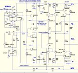
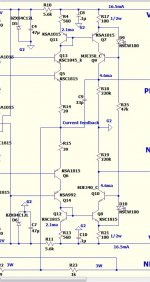
This is the accepted CFA topology being built and described: Its unique characteristics are well described by IC mfr and tech literature... some referenced back towards the beginning here.
View attachment 404164
I have been hinting for awhile that fewer parts could work well and I first published my idea for it about 35 years ago. This is where the CFA topology got bleared. If high Z values are used it may behave more like a VFA. Low Z values give some of the similar characteristics of the classic CFA, shown above. Instead of a simplified CFA, I have since called it a complimentary push-pull to differentiate it from the classic CFA topology.
Thx-RNMarsh
Thanks Richard for posting this reminder of a CFA amplifier. To my understanding, when the impedance seen looking into the negative feedback input (e.g., 1/gm of the input stage) is small compared to that of the feedback network, then it is a CFA.
Put similarly, if 100% of the current in the feedback resistor goes into the (for example) emitters of the input stage, as opposed to the shunt leg of the feedback network, then it is pretty much a "pure" CFA. It seems technically to be a matter of degree. If each of those input transistors in the complimentary arrangement are biased at 1mA, then one sees a net input impedance (1/gm) of about 13 ohms. If the shunt network impedance of the feedback network is, say, 10X this, at 130 ohms, I'd be tempted to loosely call it 90% a CFA. If on the other hand, the shunt FB element was only 13 ohms, then only about half the feedback current would flow into the emitters and I would loosely think of it being behaviorally only 50% CFA.
When we replace the BJTs with JFETs, the gm will be perhaps 10X smaller for a given bias current value. This would seem to mean that it will qualify as a CFA to the same degree if the impedances in the feedback network are on the order of 10X greater.
So it all seems to me to be a matter of degree. What percentage of the feedback current flows into the active devices as opposed to the passive shunt impedance of the feedback network.
Cheers,
Bob
Hi Bob,
I think I said the same thing a couple pages back. Or does this also appear as obfuscating?
Maybe, I just have the habit of using a different language, I suppose.
However, if it wasnt clear... i have said the same thing.... and in agreement.
THx-RNMarsh
PS - I would ask you to consider the "Classic" CFA and "Simplified" CFA a lot more , if for no other reason than it has been and is now used by many, many designers and in many, many products.
-Richard
I think I said the same thing a couple pages back. Or does this also appear as obfuscating?
Maybe, I just have the habit of using a different language, I suppose.
However, if it wasnt clear... i have said the same thing.... and in agreement.
THx-RNMarsh
I have been hinting for awhile that fewer parts could work well and I first published my idea for it about 35 years ago. This is where the CFA topology got bleared. If high Z values are used it may behave more like a VFA. Low Z values give some of the similar characteristics of the classic CFA, shown above. Instead of a simplified CFA, I have since called it a complimentary push-pull to differentiate it from the classic CFA topology.
Thx-RNMarsh
PS - I would ask you to consider the "Classic" CFA and "Simplified" CFA a lot more , if for no other reason than it has been and is now used by many, many designers and in many, many products.
-Richard
Last edited:
Østripper, For better performance or lets say lower distortion you can mirror the current over into the VAS, the extra stage does nothing good.
I get yer' drift ...
Mirror the hawksford .. 🙂
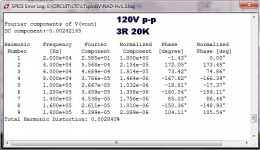
This DID bring something to the "table". In fact , exactly what I wanted.
Lower LF and HF THD at 120V p-p/ 3R loads. That's what i'm optimizing
my IPS's for these days .... as that is what is wanted. 😀 (below 1)
I can't really find any fault with (below 2) ... who would hear 28ppm
at this "ungodly" power level ? All "hail the "NX" ... very robust
design/topology - scales real nice! (82V rails) 😱
PS - I'm going through all the OPAxxx CFA IC topologies - I want
a KV/us amp !! 😀😀
OS
Attachments
Last edited:
Hi OS,
I've lost track.... did you use the triple-mirror? Results were???
The ppm for THD --- just as a point to reach for -- because its a challenge -- is .001% or less. 0.01% is too easy.
Not because its audible... it isnt as a number by itself. Its just a marker.
THx-RNMarsh
I've lost track.... did you use the triple-mirror? Results were???
The ppm for THD --- just as a point to reach for -- because its a challenge -- is .001% or less. 0.01% is too easy.
Not because its audible... it isnt as a number by itself. Its just a marker.
THx-RNMarsh
Last edited:
Oh , you like it simple. I didn't "kill anything" ??
I like it a' drippin' with parts ... 😀
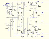
Build the VSSA 😀 ...
check out below , 14 devices.
Let me explain ....
Q5/6 and 1/2's Vbe cancel each other. This happens pretty well
on the "simple version", but with the Q13/14 "new cascode"
All these devices can be the same (ksa1015/c1815).
Use ksa992/c1845 for both the "new cascode" and the CCS's
these will also cancel. Hawksford has almost 0 co-efficient.
All is set for polar to tropics 🙂 .
PS - just 4 .37c$ mouser devices... why the drama ?
I know this will work ... because it already does (in the real world)...
Edit - your image didn't post.
That one , based on the VSSA .... has really lame LF performance. ASK NAF
he says ... " built VSSA , bass is lacking ... NAD-S has the best bass by far".
VSSA 20hz thd is 100's of PPM. And the offset floats all around at LF , as well.
OS
I like it a' drippin' with parts ... 😀
Build the VSSA 😀 ...
check out below , 14 devices.
Let me explain ....
Q5/6 and 1/2's Vbe cancel each other. This happens pretty well
on the "simple version", but with the Q13/14 "new cascode"
All these devices can be the same (ksa1015/c1815).
Use ksa992/c1845 for both the "new cascode" and the CCS's
these will also cancel. Hawksford has almost 0 co-efficient.
All is set for polar to tropics 🙂 .
PS - just 4 .37c$ mouser devices... why the drama ?
I know this will work ... because it already does (in the real world)...
Edit - your image didn't post.
That one , based on the VSSA .... has really lame LF performance. ASK NAF
he says ... " built VSSA , bass is lacking ... NAD-S has the best bass by far".
VSSA 20hz thd is 100's of PPM. And the offset floats all around at LF , as well.
OS
Attachments
Last edited:
PFC is a MUST with SMPS -
Has there been PFC applied to DIY audio amps, here? Someone suggested a motor-generator (MG) might be best of all..... not for all MG's as the distorted output can still exist there as well IF they are not PF corrected. here is the MG of a well known brand (Japanese) - using regular gasoline for fuel... before and after PFC was applied.

THx-RNMarsh
Has there been PFC applied to DIY audio amps, here? Someone suggested a motor-generator (MG) might be best of all..... not for all MG's as the distorted output can still exist there as well IF they are not PF corrected. here is the MG of a well known brand (Japanese) - using regular gasoline for fuel... before and after PFC was applied.
THx-RNMarsh
Hi Richard,
I have definitely been considering it, although it might not be a chapter. For example, it could be a section in the IPS/VAS chapter. Just not sure. If I can reach the point where I am truly confident in articulating the CFA design issues in a fair and understandable way, that would be a key to whether I would cover it and to what extent. This excellent thread has definitely sensitized me to the CFA topology. Even though I am not a strong advocate of no-NFB amplifiers, I tried to give a fair description of their design approaches and challenges, and a decent example of one. That is how I would seek to cover CFA if I do. Of course, it also comes down to time and page priorities as well. There will be a new chapter devoted to switching power supplies for audio amplifiers, which I have been doing some writing on for quite some time now. I'll have to devote more space to class D amplifiers as well.
Cheers,
Bob
I appreciate if you discuss CFA like VSSA or NX-amp variant on your next book.
I want to know:
1. what kind properties are importance for input transistor.
2. simple math to determine the slew rate.
OS Why did you KILL this topology?
I was using a 1100 watt iron, going for a 1800 watt soon on the toner transfer. Bigger copper boards with 2oz. copper suck the heat and the board etc. never gets hot enough.
Q28 and Q27 are deeply saturated and in turn saturating Q7 and Q8. They sure look cool, but they can't be helping anything.
Last edited:
OS,
Are you going to designate this as the NAD v1.3? I need to keep up and remove/purge old versions that you are going to update with circuit changes.
Are you going to designate this as the NAD v1.3? I need to keep up and remove/purge old versions that you are going to update with circuit changes.
OS,
Are you going to designate this as the NAD v1.3? I need to keep up and remove/purge old versions that you are going to update with circuit changes.
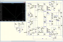
Nah , don't purge it ... the basic NAD/NX is "sweet". It by far has
the best simplicity to performance ratio.
All the new cascode/CM does is allow more low Vceo device choices
for the CF pair and offsets the "stress" (rail voltage )to the new cascode.
The CM is also more "precision" as compared to the original 820R resistor .
The 1.2 is going to be the one you can buy - it's good enough.
THIS is the thread where we just try to "push" it a little further !😀
OS
Hi OS,
I've lost track.... did you use the triple-mirror? Results were???
The ppm for THD --- just as a point to reach for -- because its a challenge -- is .001% or less. 0.01% is too easy.
Not because its audible... it isnt as a number by itself. Its just a marker.
THx-RNMarsh
With my 5-pair sim ... I get about half 28ppm (12-14) ... the OPS
is a "player" with these power levels.
As a reference , I have the genesis class A OPS. I have swapped
these iPS's to IT , and they are down to 2ppm /.0002%.
I have noticed that these CFA's are SO FAST that they actually can
try to correct the X-over distortion of my EF3. Distortion stays
lower even if the OPS is not optimally biased.
OS
- Home
- Amplifiers
- Solid State
- CFA Topology Audio Amplifiers