the big question then is how to design either one so that advantages or disadvantage are equalized...
is that even possible?
It is possible, when component technology improve 😀
I will choose VFA for sub-woofer amplifier and it is easily optimize for that. It is not require high slew rate, and then LTP current can be low, even design like SYMASYM that all transistor in IPS can use small signal transistor. It will easy to produce.
Last edited:
The "low end" (Sherwood discrete) still uses VFA .
Most "mid-fi" (marantz -accuphase) , where they don't mind to spend a
few extra $$ on boosted supplies/ extra capacitors .... see the CFA as
"the most bang for the buck" .
The original patent is interesting -Patent US4502020 - Settling time reduction in wide-band direct-coupled transistor amplifiers - Google Patents
Looks like a "VSSA" or even a 😀 mark levinson amp ! Mr. Curl ain't designing these anymore ... he hates CFA !
Looks like Levinson went from the Curl
topology to CFA before 2008. I have the 500H schema ...WOW (overkill). 😱
These "hi-ends" are just derivatives of the base topology from the patent.
(below).
OS
Attachments
Is-it a good idea ? Or to design both of them to take the best advantages of what they offer by their nature ?the big question then is how to design either one so that advantages or disadvantage are equalized...
is that even possible?
this latest result does not materially change the outcome and the conclusions, namely, that there is more gain and phase margin in a CFA that allows the loop to be closed at higher frequencies, or, if it floats your boat, closed at VFA like frequencies, but with more GM and PM.
Yes, if one does it's best to cripple the "VFA" and boost the "CFA", then you can always get "more gain and phase margin in a CFA that allows the loop to be closed at higher frequencies". The fact that it can be easily set to be the other way around is obviously irrelevant.
Not sure why people keep comparing apples and pears, that is two completely different open loop circuit topologies, but I love these "proofs" of "CFA is better", always ending with "None of the above is an endorsement of one over the other".
I a was courageous and crazy enough to begin a Hifi company, i'm not sure what will be our first power amp
Let me guess: it will be a CFA, isn't it?😉
Talking again about vested interests...
the big question then is how to design either one so that advantages or disadvantage are equalized...
is that even possible?
No, at least not before you define a metric. Starting the design process with a "VFA" vs. "CFA" decision is stupid, just get the requirements and see what fits them.
Some "CFA" topology fans say that 500V/uS makes a difference in audio (utterly nonsense).
Some "VFA" topology fans say that 0.0001% THD20 makes a difference in audio (utterly nonsense).
I say there's no need to shoot yourself in the foot, spending time and money on a high risk design (like either an ultra high bandwidth, or an ultra-low distortion). There are other more important things, like enough output current to drive even the most difficult loads, healthy stability margins under all possible external and internal conditions, and last but not the least, a healthy optimized implementation (than can otherwise ruin even the most clever design) that includes but goes well beyond the PCB layout.
What, this mean returning to the 60's-70's LIN "blameless" concept, with modern devices and perhaps with a higher order compensation beyond the standard Miller? Well, as boring as it sounds, that's about everything that the honest, non snobbish, but most demanding audiophile will ever really need. Linear audio electronics development reached it's limits and lost it's direction since before I was born. Everything since was (and still is) about better devices (like the bipolar RETs, high performance op amps to replace bulky discrete designs, etc...), customer frills, price/performance and marketing fluff.
Acoustics (speakers, etc...), Class D, perhaps DSP technologies, those are horses that may be worth placing your audio bets on.
Some "CFA" topology fans say that 500V/uS makes a difference in audio (utterly nonsense).
Some "VFA" topology fans say that 0.0001% THD20 makes a difference in audio (utterly nonsense).
Oh, yes. FM radio quality is enough 😀.
In DIY, we must try to prove all measurement figure is meaningful in listening test. Your listening pleasure is not determined by someone else, especially by Waly 😀.
If you make amplifier for other people, your amp must make them happy (I hate marketing)
...
What, this mean returning to the 60's-70's LIN "blameless" concept, with modern devices and perhaps with a higher order compensation beyond the standard Miller? Well, as boring as it sounds, that's about everything that the honest, non snobbish, but most demanding audiophile will ever really need. Linear audio electronics development reached it's limits ...
This reminds me of the blind monk in "The Name of the Rose":
"The purpose of this Abbey is the preservation of knowledge. Preservation, I say, not search for, because there is no progress in the history of knowledge."
Which specification mentions 100kHz?
I can see many @ upto 20kHz.
Is one (or more) of the IHF tests done at 100kHz?
Hi Andrew,
I took 100kHz distortion figures from the graph.
Oh, yes. FM radio quality is enough 😀.
In DIY, we must try to prove all measurement figure is meaningful in listening test. Your listening pleasure is not determined by someone else, especially by Waly 😀.
If you make amplifier for other people, your amp must make them happy (I hate marketing)
We are WAY beyond that(FM radio) , Bimo. At a certain level, "diminishing returns" ...
At low(er) levels , my 40W EF3 triple (sansui) has more LF definition than
my PPM 150W (EF2) blameless. I know why , the massive motor structure
of my dayton woofer has less effect on the EF3. This is even more evident
on my Dayton sub - the EF3 wins easily.
HF is different. The topology (CFA/VFA .. blameless) is only as good as
the OPS.
VSSA uses MOSFETS ... could the "sound" be the OP devices ?
The ONLY way to know ... is to directly swap front ends on the same
output stage.
OS
...So the question was, why are the CFA and the VFA VAS output impedances so different?...
Thank you. That must have taken a considerable amount of time and work to simulate and then write-up, and I appreciate it.
It will take a little while to think over that chunk, but what I have looked at seems to make sense.
In particular the reduced impedance of the CFA from symmetry is obvious but I never had considered it.
Despite the fact I had considered the essentially identical reduction in impedance of complementary symmetry VFA LTPs.
I notice the attached plot for effect of Ro seems to have a mistake in the on-screen text.
Not a major problem, just so you know I really did read it carefully.
Similarly in your follow-up post it looks as if the VFA and "CFA" text are transposed or else I misunderstand.
Best wishes
David
We are WAY beyond that(FM radio) , Bimo. At a certain level, "diminishing returns" ...
At low(er) levels , my 40W EF3 triple (sansui) has more LF definition than
my PPM 150W (EF2) blameless. I know why , the massive motor structure
of my dayton woofer has less effect on the EF3. This is even more evident
on my Dayton sub - the EF3 wins easily.
HF is different. The topology (CFA/VFA .. blameless) is only as good as
the OPS.
VSSA uses MOSFETS ... could the "sound" be the OP devices ?
The ONLY way to know ... is to directly swap front ends on the same
output stage.
OS
OS, I was joking.
If you can notice the different sound of many amp, Waly still do not believe you. 😀
If you make amplifier for other people, your amp must make them happy
Wrong, you must make them believe they are happy.
If you can notice the different sound of many amp
Assume you can notice the "different sound of many amps", of course, not under DBT, because DBT is (isn't it?) inherently flawed
 . Also assume, under exactly the same conditions/setup, I can't notice the "different sound of many amps".
Does this make me deaf, or make you delusional?
Not waiting for a response.
I'm still hearing a very cheap FM radio & coupled to TV antenna for better receive 🙂Oh, yes. FM radio quality is enough 😀.
....
If you make amplifier for other people, your amp must make them happy (I hate marketing)
Because I like to know what is the up to date today 😀
So don't believe what I've heard 😱
Some amp don't sound well with FM radio, some sound quite good
Even FM radio source can tell you something about your amp
Yes, the second time I try CFA is the PeeCeeBee & it is use Lat-Fet...We are WAY beyond that(FM radio) , Bimo. At a certain level, "diminishing returns" ...
....
VSSA uses MOSFETS ... could the "sound" be the OP devices ?
The ONLY way to know ... is to directly swap front ends on the same
output stage.
OS
I like the sound of it most, compare to other I've build...
So the EF3 should be sound similar(or better) to the Lat-Fet OPS
I guess it's time to try the Slewmaster 😀
That must have taken a considerable amount of time and work to simulate and then write-up,
Had the core stuff for long in my satchel, since this thread was pushed towards "mine is longer". Some editing and labeling errors are possible, haven't had the time to triple check. Where in doubt, the write-up is usually correct 😀.
Ultimately, jcx argument regarding the Bode integral is what defines the equivalence between any particular circuit topology or, otherwise said, an illustration of the TANSTAAFL principle applied to control engineering.
I'm trying in my little free time to see how the "control spillover" concept (a trivial, non critical, example is the under dampened 2nd order system overshoot) would apply to a feedback amplifier stability, and how to use this concept in systematically analyzing possible transient instabilities (like triggered by fast input signal variations, Edmonds' auto bias amplifier is a good example). Here's a good starting point.
Hi Richard,
This makes no sense to me. Please explain.
Cheers,
Bob
Hi Bob,
Maybe this will help -- More fill-in the blanks would include other generalizations, such as: Dont use dc servo to correct for basic offset.
Use it only to control thermal drift induced offset... which should be minimized to begin with.
In balanced circuits adjusting out the offset can change the THD spectrum/harmonic profile.
Here is a simple example--- 'your results may vary'. A pair of compl jFETs are trimmed for either lowest thd or lowest offset by a pot between the sources.


A dc servo could have similar affect. The trick will be in reducing offset without increasing distortion via unbalancing the circuit.
THx-RNMarsh
Last edited:
A dc servo could have similar affect. The trick will be in reducing offset without increasing distortion via unbalancing the circuit.
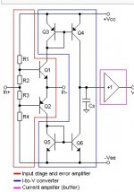
Why I chose the buffer input (non-inverting) to do this. Dealing with the offset
from the low-Z requires upsetting the Ic of the CF stage. Any way I tried it,
trimming one "side/gender" of the FB stage , trimming it's associated CSS , or offsetting
the FB node itself ..... unbalanced - higher thd.
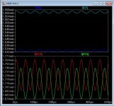
Correcting offset with the Hi-Z just requires microvolts.
disconnecting the servo will give the same plot as with it connected (no change
whatsoever)
The "leach" does this for it's
balanced input stage as well , even as it is a VFA.
PS - on the VFA "badger" , I recommend to balance as best you can with matched input pairs
as opposed to using the ("offset adj.) ...better performance with "both tails just as long" (LTP).
OS
Attachments
Last edited:
Wrong, you must make them believe they are happy.
Hmmmm.., it seem you know something about marketing that I do not know 😱.
"Perceived Value" is the term .. 😀Hmmmm.., it seem you know something about marketing that I do not know 😱.
OS
- Home
- Amplifiers
- Solid State
- CFA Topology Audio Amplifiers