Thank you , Mr. Stuart. I did already design and layout the fixed
reference version .... but soon I will be "swapping out" new designs as quick
as we produce them. 🙂
OS
reference version .... but soon I will be "swapping out" new designs as quick
as we produce them. 🙂
OS
I do and I think it your analysis in #3135 is not correct.
a) Noise # hum.
b) The way you are modeling the noise in #3135 doesn't seem to be correct (a VCCS with zero volts input?).
Reasoning for the above is that hum adds linearly as voltages (or currents), while noise always adds linearly as power. You are doing an AC (linear) analysis, so adding the VCCS may model only the hum.
Regarding the common base stage of the cascode, I could be missing something, but IMO a high Early voltage device is mandatory. Otherwise, the common base device would be subject to the same Early effect that the cascaded common emitter device is. What I'm saying is that e.g. cascoding two identical devices doesn't make much sense.
Hi Waly,
Noise from uncorrelated sources adds in squared values, but Edmond's trick tries to make the transfer from one specific noise source to the output zero. When you consider only one noise source, it cannot possibly be uncorrelated with itself.
Cascoding identical devices makes perfect sense if the device being cascoded has a low or zero impedance at its emitter. Of course you might be able to further improve performance by using unequal devices. The small-signal current flowing through the output resistance of the cascode flows back from the emitter to the collector and then cancels. This doesn't happen when the impedance from emitter to ground is low.
Best regards,
Marcel
Hi OS and Paul,
Let me explain the CCS noise cancellation in more detail and hope it will answer your questions. But first of all, I address only two aspects of the diamond IPS, thus not the cascode (and recycling of its base current), TIS or OPS.
......
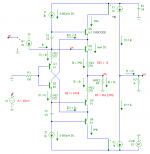
Below you see a slightly modified version of the 2nd IPS form post 3135. This one is the most easiest to analyze, as all four emitter resistors are equal, also the collectors of the first trannies are tied to the FB input and the two FB resistors replaced by equivalent parallel impedance (just for ease of calculation, later on, you can split them again).
Quite easy, isn't it? But if the collectors of Q1 and Q2 are tied to the emitters of Q3 respectively Q4, the calculation gets far more complicated. In that case I prefer to leave it to my simulator to figure that out (I'm too old for such old fashioned paperwork).
Good luck.
Cheers, E.
PS: Next project: How to recycle the base current of the cascode trannie (a la Hawksford or Baxandall).
Thank you Edmond for your in depth explanation with maths. I follow your maths. But I like the collectors of Q1 and Q2 tied to the emitters of Q3 and Q4. So madness or not I'm going to give the maths a go for this variety. Or maybe tie the collectors of Q1 and Q2 to the cascode outputs instead. This would be to gain some extra Vce across Q1 and Q2 and hopefully reduce the possible quasi saturation issues.
The "next project" sounds interesting. This issue did cross my mind the first time I used this type of input stage with cascodes. Never thought of recycling the current though.
Thanks again.
Paul
Thanks, John. I believe my question was not precise enough.It can be DOUBLE the normal F1+F2, etc It is called a TRIPLE TONE. (or TRIPLE BEAT)
Let say we are feeding an amplifier with 4 tones of different frequencies, equal levels. Their levels set in a way that their additions produce near full power at their peak, but no clipping.
Now, let-us measure IM with 2,3,4 tones.
My question is: is there always a numeric factor (with all amps) between the produced IM levels and the number of frequencies used for those IM measurements ?
And, if yes, what is this number.
I believe the most annoying combination of frequencies are the one witch gives the max IM level at around 3.5KHz, because it it the peak of sensibility of our ears at low levels.
Hi Waly,
Noise from uncorrelated sources adds in squared values, but Edmond's trick tries to make the transfer from one specific noise source to the output zero. When you consider only one noise source, it cannot possibly be uncorrelated with itself.
Cascoding identical devices makes perfect sense if the device being cascoded has a low or zero impedance at its emitter. Of course you might be able to further improve performance by using unequal devices. The small-signal current flowing through the output resistance of the cascode flows back from the emitter to the collector and then cancels. This doesn't happen when the impedance from emitter to ground is low.
Not sure I follow. What is "output zero"? Of course one noise source cannot be uncorrelated with itself.
I meant, "little sense for fighting the Early effect". Otherwise, of course the cascade is always helping with cancelling the Miller effect in the lower common emitter device (and with isolating the output from the input). From a distortion perspective, both the lower device nonlinear Miller cap and the upper common base Early voltage are important.
I learn how to improve slew rate and THD in amp design. But I still do not understand how to improve intermodulation distortion. Please some one can explain to me with simple words?
Why 2 amp with almost same THD can sound differently, especially in high frequency? I use same input and same speaker. One amp sound more detail in high frequency.
Why 2 amp with almost same THD can sound differently, especially in high frequency? I use same input and same speaker. One amp sound more detail in high frequency.
Last edited:
In what way does it contradict feedback theory? I see no contradictions and no feedback rules are broken.
As I wrote, perhaps I misunderstand, hence my curiosity to see your plots.
But I am surprised by
"A heavy hand" is a rather prejudicial metaphor.... to raise the OL gain of a CFA in the mistaken notion that more feedback is better, you end up with the OPS pole above the UG intercept ( in the open lop condition). In that case, you have to apply a heavy hand to stabilize the CFA, and you lose the benefits of wide loop gain BW, and closed loop BW...
Why can't we use the extra return ratio to lower the distortion and then "delicately" and "subtly" shape the roll-off, even add a Bode step to improve the stability?
Best wishes
David
Dave, valid points.
If you design in the extra gain, you have to deal with the extra phase shift, and as is the case with a VFA, you then have to close the loop at the requisite 1-2 MHz. I have advocated, with some caveats, that you can push it to 3 MHz - but the main point I am making here is you cannot extend the ULGF as far as you can in a low loop gain CFA.
You can of course apply advanced comp techniques . . . but what this then means is that extra compelxity has been added (to get the extra gain), and a more complex comp scheme has had to be employed to deal with the reduction in phase margin. Furthermore, you now dont have the capacitive load drive latitude that you get from a classic CFA.
The main thrust of my post was that the fact that the OPS pole lies below the UG intercept is key feature that explains why a CFA behaves very differently to a VFA - easier to comp, not gain bandwidth restricted, capacitive load tolerance etc.
BTW, I hope no one construes my comments as anti VFA and pro CFA - I am not - I am just pointing out characteristics of the topologies.
😎 (not if you are on the east coast of course)
Out of curiousity and to get an idea about the distortion, I've had a go at trying to change my wild fifth-order idea into something that at least works in LTSpice (but not in reality, as there are still plenty of loose ends).
[..]
Hi Marcel,
I follow your experiments with utmost interest. As with most multi-order systems, it is not easy to let the circuit gracefully recover from overload conditions. I hope you will go forward with this project. I know of someone who is also working on such a project, but I'm not allowed to disclose any details here. So I'll send you a PM.
Cheers, E.
PS: Regarding the PGP amp, also being a multi-order system, we sweat blood and tears to get a nice clipping behavior. Please, take a look here (at the bottom) and here how we have solved it.
BTW, this amp has also a so called "CFA" stage, though between the IPS and TIS. So, in this regard, I'm not completely off topic. 😉
[..]
Or maybe tie the collectors of Q1 and Q2 to the cascode outputs instead. This would be to gain some extra Vce across Q1 and Q2 and hopefully reduce the possible quasi saturation issues.
Hi Paul,
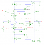
Probably, you mean connected to the emitters of of Q3 and Q4 instead (right?). Anyhow, this also is feasible, see below.
If you do it this way, Ic of Q1, which should cancel the noise or hum, has not been attenuated by the feedback resistor network, instead, it is fed through directly to the next stage (though in opposite phase). IOW, it has a greater effect than the noise at node Vn. We can compensate for this by making RE1 larger than RE2.
In the first example R6 = 2*RE2 = 26 Ohms and RE1 should be 46.3 Ohms.
In the second example R6 = 3*RE2 = 39 Ohms and RE1 should be 64.04 Ohms.
Bear in mind that the exact values depend on a lot of other things too, not only on temperature, but also on beta, the source impedance R1, etc. etc.
Notice that in the 2nd example the various currents are (almost exactly) a whole multiple of In. Just an incident when R6 = 3*RE2 ?😕
I don't know yet how to do that as simple as possible. Another issue is the temperature compensation. For a constant gm, Ic should rise with the absolute temperature, but then, other stages might be compromised. As you see there are still a lot questions to be answered.The "next project" sounds interesting. This issue did cross my mind the first time I used this type of input stage with cascodes. Never thought of recycling the current though.
You're welcome.Thanks again.
Paul
Cheer, E.
Attachments
I learn how to improve slew rate and THD in amp design. But I still do not understand how to improve intermodulation distortion. Please some one can explain to me with simple words?
Firstly you'd need to decide what kind of intermodulation distortion you're trying to optimize for. With a small number of tones there's little difference between THD and IMD - but even with few tones you can vary the phase between the components and get different IMD figures. Thus the crest factor is important. The more tones you have in your stimulus, the higher the crest factor can be.
Why 2 amp with almost same THD can sound differently, especially in high frequency? I use same input and same speaker. One amp sound more detail in high frequency.
Probably (guessing here) due to differences in PSRR. Even with flat FR some amps sound 'clouded' in HF which I attribute to noise modulation caused by insufficient PSRR at higher frequencies.
I learn how to improve slew rate and THD in amp design. But I still do not understand how to improve intermodulation distortion. Please some one can explain to me with simple words?
Why 2 amp with almost same THD can sound differently, especially in high frequency? I use same input and same speaker. One amp sound more detail in high frequency.
In the most general case, whatever you do to improve THD will improve IM, since the root-cause nonlinearity of both is usually the same.
However, be careful when you use the term THD. First of all, in the context of high-frequency distortion, the THD that is most relevant and difficult to get to small values is THD-20. THD-1 is generally of limited value. Secondly, it is really important to measure the SPECTRUM of THD-20, since single-number THD can consist of dominant and somewhat benign 2nd and 3rd order, OR equal amounts up to high order, the latter being subjectively bad, and the latter most often being caused by crossover distortion, which is bad. So single-number THD does not help us as much as we would like.
Unfortunately, proper measurement of the THD-20 spectrum can be difficult and is often not done. For one thing, many distortion analyzers cut off at 80kHz. Secondly, many audio-grade spectrum analyzers don't go high enough in frequency to measure the harmonics. My beloved HP 3580A only goes up to 50kHz, so I have to go down to THD-16 if even I only want to see the 3rd harmonic. Ditto most PC/Soundcard-based spectrum analyzers. Audio spectrum analyzers that go above 50 or 100kHz take a big jump in price.
For this reason, it is much better to use 19kHz + 20kHz CCIF IM to get an honest view of nearly all orders of the distortion.
Cheers,
Bob
The main thrust of my post was that the fact that the OPS pole lies below the UG intercept is key feature that explains why a CFA behaves very differently to a VFA - easier to comp, not gain bandwidth restricted, capacitive load tolerance etc.
Hi Bonsai,
If I am not mistaken, here you have succinctly stated why the CFP is distinguished from a VFA insofar as amount of feedback that can be used to reduce distortion. (Sometimes I am a slow learner).
So the suggestion is that the CFA topology allows us to operate at ULGF above the OPS pole, while the VFA generally does not (perhaps with the caveat that it is true for a given level of complexity of the compensation). Is this a fair way to put it?
I somehow think it is dangerous to operate ULGF above the OPS pole for any amplifier, and my knee-jerk reaction is that I can make a VFA operate with a ULGF above the OPS pole by as much as a CFA with the same level of risk with proper design of the VFA targeted to that goal. Am I wrong? Maybe I just don't understand the silver bullet of CFA that permits one to do better in regard to operating ULGF above the OPS pole.
I think we all agree that in reality there is more than one OPS pole and that it can move around quite a bit with output current, output voltage and output load. That is why I am so distrustful of it.
Cheers,
Bob
CFA unreliable ?
I have considered this. Now that I have all the OEM equivalent's of
the discussed CFA topologies - this does not seem to be an issue.
The 10 year old NAD372 ( NX - w/hawksford) has a UGLF of 1.8mhz ,
all of them are still running . Very good reviews , no magic smoke.
Marantz CFA's are mostly reliable , except for some "badcaps".
All the "pitchfork villagers" who bought these appliances (as compared to
their previous amps) - considered the CFA as " always clear,never harsh"
or "a noticeable upgrade" ... (100's of reviews by joe sixpack 😀) .
Before I commit to FR-4 , I had to explore 😀 .
A CFA will "lull" you into false sense of security. The Hawksford's local
loop would trash some of my VFA simulations (before I fixed it) while
running perfect on the CFA.
As far as the OPS , both CFA and VFA perform equally on the EF3.
OS
two thumbs Up -
You got it. And, you've had it for quit some time.... other's just needed it explained or demonstrated in many different ways and by several designs/designers until it gets across.... which i think it is, now. I found that if you tell people something that isnt explained in sufficient detail, you just get arguments and disbelief most of the time.... so you point the way and let them learn that way. Some can lead them to water but ---.
😎🙂
-Richard Marsh
Dave, valid points.
If you design in the extra gain, you have to deal with the extra phase shift, and as is the case with a VFA, you then have to close the loop at the requisite 1-2 MHz. I have advocated, with some caveats, that you can push it to 3 MHz - but the main point I am making here is you cannot extend the ULGF as far as you can in a low loop gain CFA.
You can of course apply advanced comp techniques . . . but what this then means is that extra compelxity has been added (to get the extra gain), and a more complex comp scheme has had to be employed to deal with the reduction in phase margin. Furthermore, you now dont have the capacitive load drive latitude that you get from a classic CFA.
The main thrust of my post was that the fact that the OPS pole lies below the UG intercept is key feature that explains why a CFA behaves very differently to a VFA - easier to comp, not gain bandwidth restricted, capacitive load tolerance etc.
You got it. And, you've had it for quit some time.... other's just needed it explained or demonstrated in many different ways and by several designs/designers until it gets across.... which i think it is, now. I found that if you tell people something that isnt explained in sufficient detail, you just get arguments and disbelief most of the time.... so you point the way and let them learn that way. Some can lead them to water but ---.
😎🙂
-Richard Marsh
Last edited:
I think we all agree that in reality there is more than one OPS pole and that it can move around quite a bit with output current, output voltage and output load. That is why I am so distrustful of it.
Cheers,
Bob
Then, let's all work on this aspect to limit the impact under dynamic conditions. Does the MOSFET OPS help in this regard compared to BJT? And, which OPS topology does best in this regard?
Thx-RNMarsh
Last edited:
As far as the OPS , both CFA and VFA perform equally on the EF3.
OS
Can you run a sweep on various I-V-Z and note stability/pole changes under simulated dynamic conditions. Did you do that already with EF3?
Thx-RNMarsh
I believe, yes. (While i don't know the FT of all modern power BJT).Then, let's all work on this aspect to limit the impact under dynamic conditions. Does the MOSFET OPS help in this regard compared to BJT?
In all my recent CFAs amps (all FETs) the OPS is not the dominant pole, so its influence is reduced.
As the little signal /large square waves behaviors are no very different, and can be fine tuned to be quasi identical, i believe we don't have to fear an issue.
One of the things i love with CFAs is their character don't change with volume.
I presume that the very flat temp factor of laterals offers an advantage regarding this issue too ?
Probably (guessing here) due to differences in PSRR. Even with flat FR some amps sound 'clouded' in HF which I attribute to noise modulation caused by insufficient PSRR at higher frequencies.
I don't think it is PSRR. The amp that sound worse is VFA: symetrical, input cascode, VAS cascode, and 3EF.
In the most general case, whatever you do to improve THD will improve IM, since the root-cause nonlinearity of both is usually the same.
However, be careful when you use the term THD. First of all, in the context of high-frequency distortion, the THD that is most relevant and difficult to get to small values is THD-20. THD-1 is generally of limited value. Secondly, it is really important to measure the SPECTRUM of THD-20, since single-number THD can consist of dominant and somewhat benign 2nd and 3rd order, OR equal amounts up to high order, the latter being subjectively bad, and the latter most often being caused by crossover distortion, which is bad. So single-number THD does not help us as much as we would like.
Unfortunately, proper measurement of the THD-20 spectrum can be difficult and is often not done. For one thing, many distortion analyzers cut off at 80kHz. Secondly, many audio-grade spectrum analyzers don't go high enough in frequency to measure the harmonics. My beloved HP 3580A only goes up to 50kHz, so I have to go down to THD-16 if even I only want to see the 3rd harmonic. Ditto most PC/Soundcard-based spectrum analyzers. Audio spectrum analyzers that go above 50 or 100kHz take a big jump in price.
For this reason, it is much better to use 19kHz + 20kHz CCIF IM to get an honest view of nearly all orders of the distortion.
Cheers,
Bob
Thank you, Bob. I will check in the simulation, if i reduce THD20 will IM distortion reduce too.
- Home
- Amplifiers
- Solid State
- CFA Topology Audio Amplifiers