So, we agree on this too.
About the VSSA, in order to deal with the base-emitter diode, i would had preferred an input cap than the big lytic at the emitter.
Then, try to change this cap by a BJT for DC coupling.
My proposal was this one:
http://www.diyaudio.com/forums/atta...cfa-topology-audio-amplifiers-nocap-vssa2.gif
To be improved, moving the input filter from input to the bases of the second transistors. It will add the resistance you promoted.
I am afraid that we would make a small oscillator in real life.
I would suggest something like this to add the filter and prevent oscillation in your circuit.
Attachments
The diamond has a clear benefit if you have a volume Control in front of the amplfier, then your input filter can be fixed as it can be placed behind the diamond.(like sonny is kind to show us) This also gives you free bandwidth for the compensation as it's placed outside the feedback loop.
Controversial feedback amp... "slewmaster" !
It's done (done right).
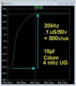
I was able to get 1/2K(500V/uS) out of this thing (below 1) !
Do we really need that ? I "slowed it down" slightly for DIY.
Mouser has 41K- ksc1845F/ 35K- ksa992F in stock @ $.21c.
No hard to find parts for this thing !
Used MJE340/350 for VAS , still ...400V/us 10ppm THD20.
Outputs can be any popular BJT OP device / drivers the same. Vbe
should be ksc3503 (high Hfe)for best thermal tracking.
EXTREMELY tolerant of mediocre components/(models).
Only way to get unstable is to omit compensation entirely.
ABSOLUTELY the best amp I've simulated.
- PSRR is -105db @1 Khz (-78db at 20hz).
- <15PPM up to 50Khz.
- 200V/uS or better .. easy, any Cdom !
- Low offset with wide adjustment. (no precision matching required)
- Capable of VERY high input impedance.
- Cool running/low current input stage/VAS.
Schema and .ASC/text below as well.
PS - UV led's for cascode are 3.1V vF - perfect !
Merry Christmas , OS
Attachments
Last edited:
Don't believe-it. My personal amp is as fast and very stable. Of course, depending of your lay-out, you need sometimes some comp adjustment, not a big deal.I am afraid that we would make a small oscillator in real life.
Don't believe-it. My personal amp is as fast and very stable. Of course, depending of your lay-out, you need sometimes some comp adjustment, not a big deal.
That is why i have set r2 to 0 - 10R.
Hey OS, are you coming up with a board layout for us to try? great design btw....
finally theory and practice has a chance to meet....😀
finally theory and practice has a chance to meet....😀
I 100% agree.That is why i have set r2 to 0 - 10R.
In preamplifiers it is too a good practive to isolate each stage (OPA or discreet closed-loop preamp) with a resistance(10-150Ohms) from the previous one.
Hey OS, are you coming up with a board layout for us to try? great design btw....
finally theory and practice has a chance to meet....😀
I tried all the varieties.
- Lazy cat/shaan's VSSA -peeceebee - simple good amps , fast. Cheap to make.
- Various OEM CFA variants.
- NX .... very well thought out design. I just did not like the zeners and
the offset "complexity". An active servo with AFEC would be a perfect
addition.
As I have stated , my CFA is the acclaimed harmon/kardon 680 OPS ,
a Luxman M120a VAS (modified) and the "spirit" of the NX.
They go very well together. The Hawksford cascode (with its local FB)
doubles the speed of the CFA.
The hawksford gives error free VAS performance by cancelling Ibc/Ibe error
currents within the cascode. You need an EF3 - I built the Hawksford/Luxman with EF2 and
it was engaging at normal volume ... but degraded with high levels.
Driving the Hawksford with a symmetrical front end is ideal , as using a
standard LTP(VFA) involves level shifting and other "dirty" asymmetrical "tricks".
This led me to find the simpler method of trimming offset. Luxman just
trims bias on the negative Hawksford semi. This will not affect the overall
symmetry of the amp, as the offset is created by Hfe/gender differences
between the active devices to begin with. Nothing in the signal path , like
with trimming the input or NFB with a DC value !
By "simming" the NX "to death" ,I found both the diamond and the 2nd stage have gain.
OLG can be increased by changing Re of either. You also can
manipulate the 2 gains independently to make this amp do other "tricks". 😀
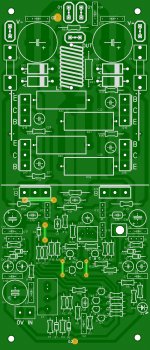
Your question of the board layout is timely. (below) is my "universal"
triple. I can add any "front end" I wish to it. Rail busses AND 2 , 3 or
5 pair options. 🙂
Whether there is any interest or not ... I will build the 3 pair version
"slewmaster"
OS
Attachments
OStripper:
Extremely well engineered, and reflects your mastery of design. You toy with the circuits and make them dance to your music, pun intended.
What is the max number of output devices the 70 volts and drivers will handle? What will that output be into both 4 and 8 ohms.
This is a great Christmas present you have made to the DIYAUDIO community.
Merry Christmas and continued blessing for the New Year to you and ALL here.
Thanks
Offered attention simple amplifier VFA wherein the output stage is built on the scheme Shiklai (with local CFA)
Figure 2 shows a diagram of Bode load change from 1 to 8 ohms
The diagram shows that the depth of NFB across the entire audible frequency range is almost constant.
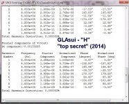
Figure 3 shows the harmonic spectrum of the signal frequency of 20 kHz with an output voltage of 30 V (peak).
As seen from the graph of the spectrum of only one third harmonic.
 [/URL][/IMG]
 [/URL][/IMG]
 [/URL][/IMG]
best regards
Petr
Figure 2 shows a diagram of Bode load change from 1 to 8 ohms
The diagram shows that the depth of NFB across the entire audible frequency range is almost constant.
Figure 3 shows the harmonic spectrum of the signal frequency of 20 kHz with an output voltage of 30 V (peak).
As seen from the graph of the spectrum of only one third harmonic.


best regards
Petr

 [/URL]
http://radikal.ru/fp/7f50548059e54fd0955bad172fd81c54]
 [/URL]
http://radikal.ru/fp/c3e3991413c745c6837f93ff1a2cae5f]
 [/URL]
 best regards
Petr
OStripper:
Extremely well engineered, and reflects your mastery of design. You toy with the circuits and make them dance to your music, pun intended.
What is the max number of output devices the 70 volts and drivers will handle? What will that output be into both 4 and 8 ohms.
This is a great Christmas present you have made to the DIYAUDIO community.
Merry Christmas and continued blessing for the New Year to you and ALL here.
Thanks
Silent night , holy night 😉 I turned the music off.
Thank you .. sir.
To answer your questions ....
If you use mje15032/33 or 2sa1837/2sc4793 (h/k uses these in the 680) ,
3 pairs are ideal ... like the "Badger".
3 pairs at 70V rails can really fill a normal living room with
breathtaking dynamics or just plain TOO LOUD !!
For my 5 pair board ... you could even do 10 pairs with NJWxxxx drivers
it could do subwoofer duty (very large subs) and 2 R loads.
3 pair would be 150W/8R (4R - lower rails)with 300+W peaks (easy).
5 pair would be 250W/8R... 400W/4R - 700w peaks.
This is what the $2400 usd H/K 990 with 5 pair MJLxxxx is rated.
If you need more than that , Class D or Sir Apex's rail switching amps
are a better bet.
It is time for the ULTIMATE VFA - CFA "RUMBLE". 😱😱
I have a VFA with 5ppm - 125V/us slew (GLA sansui - triple/Hawksford) and
this awesome design.
Same boards/layout , same VAS/OPS , one is CFA ... other is VFA.
OS
I 100% agree.
In preamplifiers it is too a good practive to isolate each stage (OPA or discreet closed-loop preamp) with a resistance(10-150Ohms) from the previous one.
yes.
Also it matters - in practice - which end you place the resistor... at the source end or at the load/input end If there is any distance/cable in between. The best location is at the distant end of the cable end (input to next amp). This is to reduce/prevent noise pickup.
Thx-RNmarsh
It is time for the ULTIMATE VFA - CFA "RUMBLE". 😱😱
I have a VFA with 5ppm - 125V/us slew (GLA sansui - triple/Hawksford) and
this awesome design.
Same boards/layout , same VAS/OPS , one is CFA ... other is VFA.
OS
😎🙂
I'm the "VFA man"... 😀
5 years to work it out. 🙂
Check it out .... No ideal current sources/voltages or
any other tricks (below). "whups" TMC comp. or a halcro amp.
2014 will be interesting.... 😀
OS
Attachments
Or better, divided in two, one in the output, one in input of next satge, when there is a cable between, to avoid capacitive loads to affect the output stage and protect against short circuit ?yes.
Also it matters - in practice - which end you place the resistor... at the source end or at the load/input end If there is any distance/cable in between. The best location is at the distant end of the cable end (input to next amp). This is to reduce/prevent noise pickup.
🙂.
I'm very impatient to hear your listening comments...It is time for the ULTIMATE VFA - CFA "RUMBLE".
May-be an idea to make both VFAs and CFAs addicts happy, to offer the two configurations on the same board ? An easy way for more people to experiment the signature differences and kill the controversies.
Anyway, congratulations.
Or better, divided in two, one in the output, one in input of next satge, when there is a cable between, to avoid capacitive loads to affect the output stage and protect against short circuit ?
🙂.
I'm very impatient to hear your listening comments...
May-be an idea to make both VFAs and CFAs addicts happy, to offer the two configurations on the same board ? An easy way for more people to experiment the signature differences and kill the controversies.
Anyway, congratulations.
I tried to do that 4 years ago - a "modular system". Now we have members
like "still4given" building 20 amps in search of the "holy grail" 😱.
The idea of the "breakoff" PCB's (like the DIYA store PS) is excellent
for ending "controversy".
H/K 680 OPS (3 pair )as a 75mm x 125mm main card ,
75mm square "daughtercard" for VFA/CFA "front end".
I did this in the "supersym" thread to compare ALL the VFA's. Luxman,Dxamp
blameless,leach ... all of them - same OPS. Thats where the "badger"
came from (AX), 🙂
PS - we could even do all the CFA "front ends" (peeceebee/vssa , NX ,others).
OS
PS - we could even do all the CFA "front ends" (peeceebee/vssa , NX ,others).
OS
let's do it right now 😎🙂 let the rumble begin until there's a tapout.
PS - who won the VFA wars? Which design?
-RNM
Last edited:
The "badger" did. Of course...let's do it right now 😎🙂 let the rumble begin until there's a tapout.
PS - who won the VFA wars? Which design?
-RNM
I'm not "pushing" DIYA's store amp - It really did stand out.
Runner up was the luxman , but it's High imp. hawksford
could not keep up with the badger's big bad CCS while using
a standard EF2.
DX , (bootstrapped vas badger) lacked the silky smooth high end.
That's why dear Carlo's(DX) amplifier "empire" followed the "blame" path.😀
Leach is "Bass king" , but DC offset... complexity/general parts count was
the downside. PS - even included predrivers on the "front end" to experience
my first true triple .... should of done this with the luxman.
Folded cascode VAS , syn08"s "VSOP" (CFA hybrid) I did hear one before 😉 ,
also was notable/reliable .... but I was a rank amateur at that time.
The EF2 was 4 pair NJWxxxx with 1.2KVA/80KuF/ 70V rails ! (badger again)
Separate 75V boosted rails for front ends /Various loudspeakers.
OS
Last edited:
- Home
- Amplifiers
- Solid State
- CFA Topology Audio Amplifiers


