parallel cap with feedback resistance
So, just a little "lead" compensation ? I'll try that and compare
to MC. Thanx.
OS
That's actually quite interesting to me.
On a particular amplifier I built the measured clipping was nice and clean, even with gross overdrive. When I simulated the circuit with models from Farichild (KSA1220AY / KSC2690AY) you'd be led to believe that the rail sticking would be so bad that just touching the rail would be the kiss of death. But reality was actually better than the simulation.
I compared the model from Fairchild to models that behaved well from Cordell and found that Fairchild included many parameters that Cordell did not make use of. So I made a copy of the Fairchild models and removed some of the parameters so that the models contained the same parameters Cordell's models use while leaving Fairchild's values intact. The result was much closer to reality than the model as provided by Fairchild suggested.
Tells me you can't necessarily trust any model until you see it behave the same in simulation as it does in reality.
I originally had trouble with the Fairchild models as well.
Cheers,
Bob
It depend of how fast are your power devices (BJT, FET) and other stages.
My way is to tune Miller for flat response in HF (no peak), parallel cap with feedback resistance for no overshoot on little square waves.
All those CFAs/VFAs behavior differences are shown here: http://www.esperado.fr/temp/VSSA/vssa-vs-vfa.html
Just be very careful to get adequate gain margin as well as phase margin.
Cheers,
Bob
My way is to tune Miller for flat response in HF (no peak), parallel cap with feedback resistance for no overshoot on little square waves.
[/url]
Found that adding a resistor in series with this cap allowed for finer tuning of the PM/GM/ULGF while keeping the amp stable in real life.
I don't quite understand ,
I used a wilson current mirror VAS , driven by a basic
CFA.
I removed all compensation .... and it is stable !
The circuit is the same , except for the wilson.
very strange ?? 😕
I ABSOLUTELY can not do this on any of my dozens of VFA
simulations or on a real amp (instant smoking zoble resistor).
It has worked that way in real built circuits as well in my experience. In fact, it is why I keep bringing the subject up. Looking for a good technical explanation. Both low HF distortion and stability is easier to come by, IMExp, with CFA topologies. And, if that was the only defining difference, it would be enough for me to use it. It just always works that way in practice.
yes, yes, I know it still needs the phase margins etc. That isn't IT. Something related to OLG/CLG and BW and phase near the upper audio freq end etc makes it simple and easy to get the compensation right... even if it isn't optimum from a BW perspective.. and have low THD. Very wide BW CFA can even be over compensated and still give excellent thd results at audio HF.
OK Now give me the 'why' as a detailed technical explanation ---
Thx-RNMarsh
Last edited:
Low HF distortion and stability is easier to come by, IMExp, with CFA topologies. And, if that was the only defining difference, it would be enough for me to use it. It just always works that way in practice.
Thx-RNMarsh
Second this from a beginners perspective. CFAs seem more tolerant when it comes to compensation. With VFAs I have struggled so far to get a good balance between THD, stability and slew rate. With CFAs adequate slew rate seems to come as standard and so far have managed two working prototypes from two attempts. Now onto a third prototype having blown up the second. 😀
Second this from a beginners perspective. CFAs seem more tolerant when it comes to compensation. With VFAs I have struggled so far to get a good balance between THD, stability and slew rate. With CFAs adequate slew rate seems to come as standard and so far have managed two working prototypes from two attempts. Now onto a third prototype having blown up the second. 😀
What about thermal stability? LC had to use an LTE431 to stabilise bias in the VSSA. I built a prototype frontend based on MagicBox's CFA (hope you dont mind!). It was a wobbly old affair. THD dropped over 50% in the first 2 or 3 minutes. Appreciate this is more to do with symmetry than CFA but the two are co-joined?
yes, yes, I know it still needs the phase margins etc. That isn't IT. Something related to OLG/CLG and BW and phase near the upper audio freq end etc makes it simple and easy to get the compensation right... even if it isn't optimum from a BW perspective.. and have low THD. Very wide BW CFA can even be over compensated and still give excellent thd results at audio HF.
OK Now give me the 'why' as a detailed technical explanation
Before finding out "why", you need to prove the facts and substantiate the details of your statement. Otherwise, "something related to OLG/CLG and BW and phase near the upper audio freq end etc makes it difficult to get the compensation right." can equally be true.
IMO, what you are saying above sounds like a safe path to a mediocre amplifier. Having a single gain stage providing the whole loop gain trends to be risky; Miller or any two pole compensation schemas (please don't mention shunt compensation, that's inferior by any perspective you are looking at it) around a very high gain stage is not easy; the Miller loop itself may be unstable and oscillate at something like 30MHz. Unless you are happy with low loop gains (because you are not hunting for distortions comparable to optimized VFAs) the Miller loop needs to be itself compensated, usually by a lead-lag network at the TIS output.
But then of course, there's always the argument of "sounds good enough", 0.01% is enough, etc... so there's obviously no clear cut and no definitive requirements. The risks of starting a discussion about CFA, without having any pre-defined metrics.
tapout, That's related to the biasing method used in that specific design, not a generic CFA property. I've designed and built 2 CFA's over the last 18 months and DC and bias stability wise they are remarkably stable. On both my designs, I used a diamond front end, and arranged it so that all of the transistors see the same Vce and same Ic. Drift and offset cancel. Once warmed up, and the offset dialed out, the amplifiers both exhibit a stable 1-2 mV of offset - repeatable over many on- off cycles. Given the low loop gains, this is a very good result in my view - fully DC coupled and no servo.
For OPS bias stability, I get about 40mA or so change from cold to hot on the nx-Amp, also very repeatable. The sx-Amp used a class A bias clamp, and is much more stable, given the 1.4 A OPS bias current.
For OPS bias stability, I get about 40mA or so change from cold to hot on the nx-Amp, also very repeatable. The sx-Amp used a class A bias clamp, and is much more stable, given the 1.4 A OPS bias current.
You need to make sure that your ULGF is consistent with sufficient phase margin. If you set the ULGF for say 1.5 MHz on a CFA and VFA to cater for the OPS pole, the loop responses are remarkably similar - both loop (above the -3 dB BW) and closed loop response.
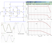
Looks like unstable, but it is very stable, know what happen?

Attachments

....
But then of course, there's always the argument of "sounds good enough", 0.01% is enough, etc... so there's obviously no clear cut and no definitive requirements. The risks of starting a discussion about CFA, without having any pre-defined metrics.
Wally, any definition of an amplifier should be? could you post your quality margin?
It depend of how fast are your power devices (BJT, FET) and other stages.
My way is to tune Miller for flat response in HF (no peak), parallel cap with feedback resistance for no overshoot on little square waves.
All those CFAs/VFAs behavior differences are shown here: http://www.esperado.fr/temp/VSSA/vssa-vs-vfa.html
Yes, the closed loop responses will be a little different because of the independence of BW vs gain in a CFA and in a VFA they are interdependent.
For response peaking in CLG gain, you can also use a filter in front of the + input. This can allow you to keep the high SR in many cases, rather than lowering the loop ULGF, which is another route to solving this issue. I have a section on this very subject in my sx-Amp write up with some plots.
IMO, what you are saying above sounds like a safe path to a mediocre amplifier. Having a single gain stage providing the whole loop gain trends to be risky; Miller or any two pole compensation schemas (please don't mention shunt compensation, that's inferior by any perspective you are looking at it) around a very high gain stage is not easy; the Miller loop itself may be unstable and oscillate at something like 30MHz. Unless you are happy with low loop gains (because you are not hunting for distortions comparable to optimized VFAs) the Miller loop needs to be itself compensated, usually by a lead-lag network at the TIS output.
What is the definition of a mediocre amplifier? Do you need a crazy high loop gain in the first place? Can you not aim for linearity instead? My personal aims are single digit ppm THD or lower (at least in sims as I don't have access to the necessary measurement equipment at present). Massive slew rate is unimportant to me (although this is said to be the CFA strength) as long as it is above 60v/us.
Linearity seems a safer way to proceed to me at present as you don't need to aim for high ULGFs which makes getting good PM/GM easier as the output stage pole becomes less significant.
Agree with your comments about compensation. Another personal goal is to reduce the TIS loading as much as possible. Thinking about using a diamond buffer straight after it in my latest experiment. Leaving the only significant loading being the lead-lag compensation to stabilise the miller loop.
I Can't read your picture correctly - you need to plot the loop gain and phase Ontoaba.
It is voltage follower, gain =1 or all gain feed to FB.
Attachments
could you post your quality margin?
The question is legitimate and I do not have a precise answer. However, without setting S.M.A.R.T. objectives, an intelligent engineering discussion is barely possible. I will always end up in "my word against yours", etc...
What is the definition of a mediocre amplifier? Do you need a crazy high loop gain in the first place? Can you not aim for linearity instead? My personal aims are single digit ppm THD or lower (at least in sims as I don't have access to the necessary measurement equipment at present). Massive slew rate is unimportant to me (although this is said to be the CFA strength) as long as it is above 60v/us.
Linearity seems a safer way to proceed to me at present as you don't need to aim for high ULGFs which makes getting good PM/GM easier as the output stage pole becomes less significant.
Agree with your comments about compensation. Another personal goal is to reduce the TIS loading as much as possible. Thinking about using a diamond buffer straight after it in my latest experiment. Leaving the only significant loading being the lead-lag compensation to stabilise the miller loop.
Single digit ppm distortions (I suppose at HF) without high loop gain is not possible. For example: if your Locanthi triple output stage has at 20KHz 0.1% (usually 3rd harmonic) open loop distortions, then you need a total of 60dB loop gain at 60KHz to get the distortions down to 1ppm. Assuming a single pole compensation, that would mean an ULGF of no less than 60MHz, which is impossible to get, since power bipolars have an Ft of max. 30MHz. You could add output devices (depending on the minimum load impedance) to lower the output stage open loop distortions to 0.01%, then you need only 40dB of loop gain at 60KHz, or an ULGF of 6MHz, still to high for a practical implementation. Consider a two pole compensation schema, and you could get the ULGF down to 3MHz, still rather on the high side. Use a high order compensation schema like the NDFL and you could get the required ULGF down to 1.5MHz, which is already practically feasible.
But then 40dB loop gain at 60KHz with a decent phase margin can easily be considered as very high. Certainly beyond the reach of a standard compensated CFA.
The example is of course extreme, just to show the arithmetic of loop gains and distortions.
Yes Bonsai.For response peaking in CLG gain, you can also use a filter in front of the + input. This can allow you to keep the high SR in many cases, rather than lowering the loop ULGF, which is another route to solving this issue.
I use low pass input filter to optimize square waves between large signals and little ones. I must said "i used", as i use it, with listening comparisons, for the best music reproduction i can. A lot lower FC, each time.
I believe a compromise between margin and phase turns at 20kHz ?
This said, one advantage of DIY is you can have a very stable amplifier *in your set-up* with little phase margin. Nothing you can risk with a mass market industrial product where you don't know all the loads and sources your customers can imagine. ;-)
Last edited:
Single digit ppm distortions (I suppose at HF) without high loop gain is not possible. For example: if your Locanthi triple output stage has at 20KHz 0.1% (usually 3rd harmonic) open loop distortions, then you need a total of 60dB loop gain at 60KHz to get the distortions down to 1ppm. Assuming a single pole compensation, that would mean an ULGF of no less than 60MHz, which is impossible to get, since power bipolars have an Ft of max. 30MHz. You could add output devices (depending on the minimum load impedance) to lower the output stage open loop distortions to 0.01%, then you need only 40dB of loop gain at 60KHz, or an ULGF of 6MHz, still to high for a practical implementation. Consider a two pole compensation schema, and you could get the ULGF down to 3MHz, still rather on the high side. Use a high order compensation schema like the NDFL and you could get the required ULGF down to 1.5MHz, which is already practically feasible.
But then 40dB loop gain at 60KHz with a decent phase margin can easily be considered as very high. Certainly beyond the reach of a standard compensated CFA.
The example is of course extreme, just to show the arithmetic of loop gains and distortions.
Thank you for your explanations. It helps piece my limited knowledge together. Need to get a handle on NDFL it seems. No matter how many times I read the cherry paper on NDFL I get the concept but not the practical implementation.
From my limited experimentation it would appear 3Mhz ULGF is possible but very difficult to stabilise. Anything less than 1.5Mhz is pretty straight forward.
Just remembered your "slice and dice" comment about loop gains. Error corrected output stages allow for a lower global loop gain around them but add up the totals and it makes sense when looking at THDs and the arithmetic.
There is much to absorb when it comes to analogue electronics...
It is voltage follower, gain =1 or all gain feed to FB.
I still don't see your loop gain plot Ontoaba
- Home
- Amplifiers
- Solid State
- CFA Topology Audio Amplifiers