Ostripper,
I assume your question was in relation to the VSSA front end vs the Sansui circuit on the previous page.
In the Sansui circuit, the front end JFET LTP is fed from a current source. It is therefore not a CFA for the reason outlined below.
In a CFA, the TIS input current is set by the value of the feedback resistor, so it in fact can be very high to meet the demands of the loop - this is where you get the 'current on demand' behavior from. As an example, I modelled a CFA with a standing current of 2.5mA on the front end which delivered a peak current of 8mA in response to a very fast high amplitude square wave. In a VFA, the peak current into the TIS is set by the LTP current. To get the same performance out of VFA, you need to go to MIC - its difficult to to do it with MC 'blameless' compensation methods.
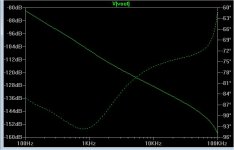
Secondly, in a CFA, the CLG -3 dB bandwidth (within reason) is pretty insensitive to the actual gain setting - in a practical CFA amp, you can vary it over a 20 dB range, and the -3 dB bandwith only moves by a few kHz. In a VFA, the -3 dB BW is linked to the CLG - this is a function of the dominant pole compensation. You don't need to apply dominant pole comp in a CFA to make it stable. However, because of the output stage pole, in practice, the performance of CFA's and VFA's above the -3 dB loop gain bandwidth is very similar because you have to close the loop at between 1-3 MHz assuming fast OP devices + Zobel and inductor.
The Sansui circuit does not use dominat pole comp, but they they have loaded the VAS and used a comp network across the LTP drain loads, so I suspect it will be quite fast.
I have a short write-up on this stuff on my website.
I assume your question was in relation to the VSSA front end vs the Sansui circuit on the previous page.
In the Sansui circuit, the front end JFET LTP is fed from a current source. It is therefore not a CFA for the reason outlined below.
In a CFA, the TIS input current is set by the value of the feedback resistor, so it in fact can be very high to meet the demands of the loop - this is where you get the 'current on demand' behavior from. As an example, I modelled a CFA with a standing current of 2.5mA on the front end which delivered a peak current of 8mA in response to a very fast high amplitude square wave. In a VFA, the peak current into the TIS is set by the LTP current. To get the same performance out of VFA, you need to go to MIC - its difficult to to do it with MC 'blameless' compensation methods.
Secondly, in a CFA, the CLG -3 dB bandwidth (within reason) is pretty insensitive to the actual gain setting - in a practical CFA amp, you can vary it over a 20 dB range, and the -3 dB bandwith only moves by a few kHz. In a VFA, the -3 dB BW is linked to the CLG - this is a function of the dominant pole compensation. You don't need to apply dominant pole comp in a CFA to make it stable. However, because of the output stage pole, in practice, the performance of CFA's and VFA's above the -3 dB loop gain bandwidth is very similar because you have to close the loop at between 1-3 MHz assuming fast OP devices + Zobel and inductor.
The Sansui circuit does not use dominat pole comp, but they they have loaded the VAS and used a comp network across the LTP drain loads, so I suspect it will be quite fast.
I have a short write-up on this stuff on my website.
Last edited:
I would think (but I'm not a great thinker) that "modulation" of the current through the input device has more to do with CFA, than setting of the quiescent current has in defining whether it is a CFA....................................
In a CFA, the TIS input current is set by the value of the feedback resistor, so it in fact can be very high to meet the demands of the loop - this is where you get the 'current on demand' behavior from.....................
Diamond names are everywhere.
The Sansui Diamond circuit is a very fast VFA :
200 V/µS has been stated for it.
Its idea relies on making a push-pull VFA from a single differential input.
.
The Sansui Diamond circuit is a very fast VFA :
200 V/µS has been stated for it.
Its idea relies on making a push-pull VFA from a single differential input.
.
I agree with you Andrew, CFA has nothing to do with the way the current is set. it has to with weather you inject the FB in a high impedance- or in a low impedance node in the circuit. A CFA can just as well as a VFA be driven by constant current sources.
The sansui is a VFA- as the FB is injected as a voldtage-drive to the on the backside of the input LTP
I don't think I mentioned how the quiescent current was set in my explanation. The main point is it's the feedback resistor that sets the peak current into the TIS. In a VFA, the peak current cannot be higher than the LTP current. This is and the fact that you don't need dominant pole comp means you can get very high slew rates. Secondly, in a classic VFA the CL BW is linked to the gain. In a CFA it's not.
So, it has nothing to do with the fact that you inject the feedback into a high or low impedance node.
So, it has nothing to do with the fact that you inject the feedback into a high or low impedance node.
So, it has nothing to do with the fact that you inject the feedback into a high or low impedance node.
CFA -- The topology determines this condition of operation which you have described correctly.
THx-RNMarsh
Very nice one. Mark alexander's like.Thanks Richard, basic model for truly DC coupled CFA is attached.
This said, i would like we explore a little more about so called 'diamond buffers'.
It change a little the feedback phases at HF, because the base's capacitance of the real input stage (the one with feedback) are reduced. So, need a little tweak to be compared fairly.
One track: to add a serial resistance between emitter of the first transistors and the base of the second ones ?
I see no reason we cannot achieve a good sounding result, with the added advantages: better isolation, higher input impedance, less current gains in the second transistors. Lower overall distortion.
Something about Mark Alexander solution i like very much: using a current mirror, and if the first stage has some gain (he use an OPA), when the first stage reach its flat open loop limit, its efficiency begin to reduce itself as frequency increase. Need more current to achieve the same level. So it is a kind of pre-accentuation witch can compensate the following stages open loop frequencies decreases, independently from the feedback. I don't know if i'm clear.
Last edited:
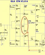
Just to clarify the 2 circuits (neither is the sansui) just the OPS is !
1.(A) - my first circuit - former member SYN08 designed a similar amp ,
it had a gain of 10 and used an input OP-amp for additional gain +
DC compensation.
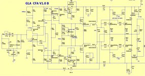
2.(B) The "peeceebee" version.
Both use the 20-50ma high current divider for FB. The second circuit
"splits" FB and dumps most of this current through C10/11. My capacitance
multipliers allow for smaller caps at c10/11 , but it is still a "peeceebee".
I've outlined the FB on both , simulated both (real close) ....
I'm quite impressed with both , they beat my best VFA ..easily.
OS
1.(A) - my first circuit - former member SYN08 designed a similar amp ,
it had a gain of 10 and used an input OP-amp for additional gain +
DC compensation.
2.(B) The "peeceebee" version.
Both use the 20-50ma high current divider for FB. The second circuit
"splits" FB and dumps most of this current through C10/11. My capacitance
multipliers allow for smaller caps at c10/11 , but it is still a "peeceebee".
I've outlined the FB on both , simulated both (real close) ....
I'm quite impressed with both , they beat my best VFA ..easily.
OS
Attachments

I agree with you Andrew, CFA has nothing to do with the way the current is set. it has to with weather you inject the FB in a high impedance- or in a low impedance node in the circuit. A CFA can just as well as a VFA be driven by constant current sources.
Well then you should rewrite the books and literature by the greats like Jung, Gilbert, Williams and many others, they all wrong. Darn I wasted a couple of months at varsity studying the CFA topology. If I cant trust their pioneering analogies and theories then I cant trust any electronic knowhow by them either.🙁
Thanks Richard, basic model for truly DC coupled CFA is attached. Input pair biasing made by same base-emitter diodes like input pair has, no out-of the feedback buffer here. Basic model for exploring further.
The reason for adding a buffer to the + input of the CFA was to limit loading on the signal source.... provide a high Z load for the source signal. Be it diamond buffer or any other.
That may not be needed with some signal sources.... if CFA input Z is >600/10K.
Thx-RNMarsh
peeceebee is "sehr gut" !
PSRR was my only issue - solved that (below 1).
Added the awesome H/K 680 Vbe , checked the REAL amp ...
675R gave me 80mA/device - simulator with sc3503=660R. (below 2)
All else is just fine , THD /transient response.
I'm happy 🙂 ! What a simple amp !
OS
PSRR was my only issue - solved that (below 1).
Added the awesome H/K 680 Vbe , checked the REAL amp ...
675R gave me 80mA/device - simulator with sc3503=660R. (below 2)
All else is just fine , THD /transient response.
I'm happy 🙂 ! What a simple amp !
OS
Attachments
Now we enter in the interesting area of this thread: real builds and comments about listening results...I'm happy 🙂 ! What a simple amp !
About musical details, ease of the reproduction and listening fatigue...
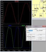
one last test - it WILL be overdriven !
Clips VERY symmetrical (below) at 53V..+/-.1v (60V rails).
I lowered my 2 - 47pF compensation caps to 15pF to get
damped ringing - I'm most likely overcompensated.
But , at 47pF ... still over 120V/uS.
ONLY 6 semi's in the whole "front end" ,
The down side is the need for cap multipliers and
the 4 large 470uF@100V caps.
What you save on semi's you spend on caps 😀 .
Any suggestions on improvements ?
OS
Attachments
Clips VERY symmetrical (below) at 53V..+/-.1v (60V rails).
I lowered my 2 - 47pF compensation caps to 15pF to get
damped ringing - I'm most likely overcompensated.
But , at 47pF ... still over 120V/uS.
ONLY 6 semi's in the whole "front end" ,
The down side is the need for cap multipliers and
the 4 large 470uF@100V caps.
What you save on semi's you spend on caps 😀 .
Any suggestions on improvements ?
OS
Os, did you follow this thread from beginning? We vent all that steps already.
Now we enter in the interesting area of this thread: real builds and comments about listening results...
About musical details, ease of the reproduction and listening fatigue...
I already know how the OPS behaves. 20 years durability , 1mv bias
accuracy and excellent damping/stabilty. (it's been reviewed - H/K680)
Harman Kardon HK 680.
BTW - I also own one (from the dumpster).
What I want to know (being a VFA man 😀) , is what all the "fuss"
is over CFB. Never DIY'ed one.
My concern layout wise ..is the high current FB network + C10/11.
With 20+ ma passing through those caps , one would not want to
ground them to the "clean" ground. Also , unlike a VFA , routing the FB
to the input pair will be harder (maybe).
I'll have to look at the VSSA,PeeCeeBee, and all the other CFA builds for
ideas.
I have the OPS/VAS + cap multipliers already designed on Sprint. I
just need to add the CFA "front end".
OS
Os, did you follow this thread from beginning? We vent all that steps already.
No , just kept in " VFA world" until days ago.
Almost 2500 posts , I could design/build/test a couple amps in the time to read
all that. 😀 I will just digest small portions in a timely manner.
This thread is almost to "blowtorch" proportions 😱 .
OS
No , just kept in " VFA world" until days ago.
Almost 2500 posts , I could design/build/test a couple amps in the time to read
all that. 😀 I will just digest small portions in a timely manner.
This thread is almost to "blowtorch" proportions 😱 .
OS
Wellcome here, for me it is a new world too.
Well then you should rewrite the books and literature by the greats like Jung, Gilbert, Williams and many others, they all wrong. Darn I wasted a couple of months at varsity studying the CFA topology. If I cant trust their pioneering analogies and theories then I cant trust any electronic knowhow by them either.🙁
CFA is now means Controversial Feedback Amplifier, you can't judge who is right or who is wrong. With VFA-CFA feedback classification some amplifier cannot be classified to CFA neither VFA, for example a singleton input amplifier.
Just take it as is, and you also could name your own version like IFA, BFA, TFA, WFA, DFFA, etc.
I have to disagree, its not about who is right or wrong, The CFA was called as such for reason that have nothing to do with the feedback. This is not a VFA/CFA classification. When someone else now decides that it should be called as such because of the feedback action causes confusion and misunderstanding of the topology. We must stick to the industry explained and accepted reason CFAs are called as such.
- Home
- Amplifiers
- Solid State
- CFA Topology Audio Amplifiers