Good question and to one of the main points to be discovered from this "exercise'. We need to push the topology harder than 50W.... to see quicker and easier what falls out of this. I have no idea why that number was chosen - other than to compare against already made VFA, perhaps. No amp at 50W is useful to me because my speakers are low efficiency. It is also more likely to run into compression/overload/clipping/higher thd etc. My own test data example that I put up was well over 200W at the test equipment limit of about -100dB. [however, I can now measure with accuracy and confidence to much lower levels - but don't have the amp here at the moment].
Lets find the break points.... I suggest push the SR as one of those break points. Make the 50W scalable to higher power levels and take a look.
Thx-RNMarsh
Richard, all CFA amps I presented here are in 120W range or more as in my 200W CFA thread. My choice to show distortion at 50W was just intention to easy comparison between amps.
Regarding Slew Rate(SR) what you think is high enough? 200V/usec is not high enough? What are you arguments to boost it higher?
BR Damir
I'm not sure to understand your question (my poor English).What is considered the fastest output type transistor seeing as that is the limitation with slew rate?
Power fets are usually faster than power bipolars. ( Look at both slew rates in Dadod's babies.) Reason why they are used in most Class D amps. In fact all the stages are very close in regard to bandwidth, and stability can be a problem with at least 18db/oct around 10MHz.

To all concerned...
This thread is currently one of the most troublesome on the forum. Any further posts that show even a hint of sarcasm, sniping, trolling etc will be deleted and if deemed necessary the poster of such material will be issued with penalties.
I try cap multiplier which designed by Rod Elliot to my variant of VSSA. Voltage ripple before cap. mult. is 120mVpp without input signal and I can not see a ripple on my scope after cap. mult.
But sound quality is worse, especially at high frequency. I do not have distortion meter, so I can not confirm the distortion of high frequency.
Classic cap multipliers sound much worse than real caps to my ears. No experience yet with the newly developed variants.
I'm going to try & summarize my CFA journey in SPICEland. First, I need to declare my prejudices.
I don't think zillion V/us is necessary for good sound .. nor is <1 pp zillion THD. Neither are noveau circuit topologies of interest to me UNLESS they provide something which I can't achieve with old fogey Jurassic techniques.
My obsession is always simplicity. A design that achieves SOA performance with half the active & passive bits of lesser designs is to me, a good design and is what engineering is about.
My other obsession is Blind Listening Test to Lipsh*tz & Vanderkooy bla bla standards. In my previous life, I was a true DBLT guru and the small number of such tests I've conducted on amps suggest for a given tech. performance, simpler always SOUNDS better.
In fact, they also suggest that simpler designs with lesser tech. performance, THD bla bla may often SOUND better than complex designs with supa dupa tech. performance but I have insufficient data to pontificate about this point ..
A possible reason (and another obsession) for this result is that simpler amps usually have better overload and recovery behaviour and this is likely the main audible difference between amps of about 50W 8R. see Bob Cordell's book.
CFA amps for me, are just a tool to achieve my aims. I have no religious attachment. They simplify certain things eg no need to worry about Slew Rate.
But they also seem to demand 'symmetrical' topologies which introduces many problems which are responsible for some of the myths about CFAs.
IMHO, identifying these problems is the first step towards better CFAs. I don't have sensible answers to these problems at the moment but its vital to always keep them in mind. Adding extra complexity which doesn't address them is non-productive.
________________
My usual caveat that I've never burnt solder on such exotic beasts unlike VFAs where I've considerable 'real life' experience to back up my pontificating.
Last edited:
The starting point is the simple CFA in my #500 post.
The LG here (as with nearly all 'symmetrical' amps) is limited by R1/3 vs R6/R10. This suggests that VASs with less hfe but better Ccb would improve performance.
Doing this and some small tweaks gives the attached circuit.
It still uses the yucky compensation in #500 but in fact, cleverer stuff isn't better. The performance of this circuit is already close to the max that can be extracted from these devices.
LF THD is @ 10ppm with 20kHz @ 20ppm but note higher order harmonics are some 20dB below 2nd & 3rd. This is due to the partial Cherry compensation via C5.
This is about the simplest possible CFA with 11 active devices.
Attachments
In my #530 post, I point out that there are 2 obvious ways to 'improve' the simple CFA.
______________
Enhancing the VAS, ala Blameless would give less than 6dB improvement in LG and hence THD cos the R1/3 vs R6/R10 limitation. But it should greatly reduce evil Ccb modulation and give much better HF THD.
This is confirmed in #825
______________
The other route is to use evil Locanthi triples which gets around the R1/3 vs R6/R10 limitation. Sure enough, LF THD is greatly reduced but HF THD isn't cos evil modulated Ccb isn't addressed.
I've finally got some success using 'advanced' compensation (thanks to Damir and particularly Andrew) but in fact, there's not much difference compared to yucky Cherry+Miller on this circuit .. which suggests we are already wringing the best THD performance out of this circuit.
13 devices which makes it as complex as the simplest possibly VFA in my #502 post but better performance all round.
______________
Enhancing the VAS, ala Blameless would give less than 6dB improvement in LG and hence THD cos the R1/3 vs R6/R10 limitation. But it should greatly reduce evil Ccb modulation and give much better HF THD.
This is confirmed in #825
______________
The other route is to use evil Locanthi triples which gets around the R1/3 vs R6/R10 limitation. Sure enough, LF THD is greatly reduced but HF THD isn't cos evil modulated Ccb isn't addressed.
I've finally got some success using 'advanced' compensation (thanks to Damir and particularly Andrew) but in fact, there's not much difference compared to yucky Cherry+Miller on this circuit .. which suggests we are already wringing the best THD performance out of this circuit.
13 devices which makes it as complex as the simplest possibly VFA in my #502 post but better performance all round.
Attachments
Last edited:
If we can somehow get around the R1/3 vs R6/10 stop gap in LG for the Enhanced VAS EF2 simple CFA, we have the possibility of SOA performance with very simple circuits.
We do this by feeding R1/3 from separate high voltage rails V6/7 and adjusting accordingly. This is less than 2ppm THD 20kHz 50W 8R and less than 0.1ppm below 4kHz.
It makes nonsense of the belief that CFAs are inherently limited in their THD performance. The THD limitation is almost certainly due to the 'symmetrical' topology used and probably a feature of VFA 'symmetrical' topologies too.
It has 13 devices, same as the simplest possible VFA eg my #502 design but nearly SOA performance. I've no doubt that a little more tweaking would get even 20kHz THD below 1ppm.
Alas, this particular circuit is definitely in the 'hand carved by virgins' category (though not from Unobtainium 🙂) It might be sensible if you are considering separate supplies for the VAS & IPS.
But R1/3 need tweaking for sensible VAS currents. I tend to use less VAS current than Bob Cordell, Bonsai or Dadod so they may be less concerned.
I offer it as an indication of where we need to go for better CFAs.
___________________
Where do we go from here?
An obvious route is to combine evil Locanthi triples to get more loop gain and the Enhanced VAS to deal with modulated Ccb.
This is essentially what Bonsai does in his qx-Amp. Dadod has come from the Dark Side, really complex circuits, to the same topology. This has 15 devices if you don't use a cascoded i/p like they do .. less than my #499 circuit with performance in #823
I have to give Bonsai/Dadod my CFA vote at the moment though I have misgivings about more complex compensation around Enhanced VAS + evil triples.
And this more complex topology doesn't have the performance demonstrated here.
It would be nice to be able to solve 'R1/3 vs R6/10' with only an extra 2 devices and that would be my idea of 'improved CFA'. Need serious thought & work to do this elegantly.
Attachments
Last edited:
Some loose ends
Final caveat about not having burnt solder and more importantly ... not conducted Double Blind Listening Tests bla bla
- Simple CFA IPS like VSSA and my efforts are likely to have up to 3dB better THD than Diamond IPS until THD drops below 1ppm.
The con is large evil electrolytics.
There doesn't seem to be a DC offset advantage to Diamond IPS; both have to be tweaked or use a servo. Bonsai's AFEC may be the way to get both your DC servo and enough extra LG to get below 1ppm @ 20kHz
There is a caveat about consistency of VAS current with simple CFA input. LC quotes 12-15mA but it is likely that Diamond IPS has a similar inconsistency as the mechanism for this are the same in both cases.
I have no practical experience on this important point.
- Mythbuster 1 : Simple CFA has the lowest noise of any sensible Power Amp IPS topology. Quieter than VFA LTPs
- Mythbuster 2 : In all the examples I show, IPS/VAS is the dominant THD mechanism. The Output stage distortion is represented by the higher order harmonics in the Distortion plots and is usually 20dB below the 2nd & 3rd due to the IPS/VAS interaction.
This shows the foolishness of considering IPS/VAS as separate blocks and looking at their performance with perfect OPS.
Proper integration of VAS & OPS with appropriate 'advanced' compensation can make OPS distortion a secondary instead of their usual primary influence in more naive topologies.
- I've glossed over compensation issues but the integration of the VAS and the OPS is critical to SOA performance with simple topologies. Compensation issues are a vital part of this and I've used different compensation in my various examples as appropriate.
The ease which different topologies can use (and benefit) from 'advanced' compensation is one of their most important features.
My eyes glaze over when I see a supadupa OPS with similar complexity to my WHOLE amplifiers and with LESS performance.
Final caveat about not having burnt solder and more importantly ... not conducted Double Blind Listening Tests bla bla
Last edited:
It makes nonsense of the belief that CFAs are inherently limited in their THD performance. The THD limitation is almost certainly due to the 'symmetrical' topology used and probably a feature of VFA 'symmetrical' topologies too.
Actualy all topologies are linearity bound and VFAs make no exception
but in their cases said limitations can be removed thanks to local
feedback loops , ie , NDFL or other error correction schemes that
are more or less easily implementable in theses kind of amplifiers.
This current is to help the power mosfet to slew fast even at high levels despite its high gate parasitic capacitance.There is a caveat about consistency of VAS current with simple CFA input. LC quotes 12-15mA
In my own simple CFA, 6 ma gives better distortion number, slower slew rate, sound not so good.
Last edited:
There's loadsa pertinent stuff in my #1299 post too.
The bigger R1/3 'current drives' the VAS in #1431 with its pros & cons.
As I said at the start, my aim is supa dupa performance without da complexity.
I'm quite happy if you do supa dupa complex circuits ... as long as you actually have better performance than my simple, naive Jurassic efforts.
The bigger R1/3 'current drives' the VAS in #1431 with its pros & cons.
The REALLY big advantage of LTP VFA topology is the current mirror on the IPS which deals with both IPS & VAS THD mechanisms AND their interaction AND gives loads more LG .. without VAS current stability problems.wahab said:Actualy all topologies are linearity bound and VFAs make no exception but in their cases said limitations can be removed thanks to local feedback loops , ie , NDFL or other error correction schemes that are more or less easily implementable in theses kind of amplifiers.
As I said at the start, my aim is supa dupa performance without da complexity.
I'm quite happy if you do supa dupa complex circuits ... as long as you actually have better performance than my simple, naive Jurassic efforts.
There is a caveat about consistency of VAS current with simple CFA input. LC quotes 12-15mA
Actually I think this variation is acceptable, especially if you run high VAS currents like Cordell, Bonsai & Dadod. It's just that I don't have any 'real life' experience on this so must take LC on trust. If I was making a commercial CFA, this is one of the first 'real life' things I must investigate.Esperado said:This current is to help the power mosfet to slew fast even at high levels despite its high gate parasitic capacitance.
Last edited:
Richard, in a practical amplifier i think the OPS will be the biggest contributor of distortion. Typically you can expect 0.1 to 0.2 % for a class AB circuit. As you drive it harder, you will see the characteristic 'load hump'.
Re the TIS current, if the degen resistors are large enough the current distribution from unit to unit is very tight and stability with temp is also good.
I have commented on this in my updated nx-Amp write up. I think the biggest issue is to make sure when simming that you use good models that accurately reflect the devices used. As you noted in your sim of the nx-Amp, this made a big difference in THD results ( thanks for doing that btw - appreciate it).
Last edited:
I like the current on demand feature of CFA. I did some sims and got 1:8 change in diamond output current with the input stage still remaining in class A. Ok, I had to feed a very large, fast rise time signal to get this, but it's interesting to contrast this with VFA where the peak current into the VAS is the same as the tail current. The importance of sizing the feedback resistor correctly in a CFA cannot be overemphasized. To keep the front end in class A, just make sure the peak feedback current is less than the IP stage level shifter standing current.
That's the case with naive topologies like Blameless with Miller comp. where the OPS is considered a separate block.Richard, in a practical amplifier i think the OPS will be the biggest contributor of distortion.
Once you start using TMC & Cherry with appropriate topologies, this is no longer the case .. certainly at the 50W 8R level.
You'll note from my distortion curves that the higher order harmonics start rising with frequency though they are still well below 2nd & 3rd in my examples at 20kHz.
I was already seeing this 'real life' behaviour in the early 90's though devices weren't as good as we can get today.
The better topologies & compensation make the evil xover and gm doubling distortions in Self much less of a problem. It's down to better integration of VAS & OPS.
The 'remaining' OPS distortions, like Beta droop, are less yucky and also more amenable to feedback.
When you get to 200W 8R, I certainly expect to see OPS start dominating again. When we get some reliable EKV models, I hope to show how output FETs may delay this further.
There's a lot of misunderstanding about 'slow' output devices. The important effect is that compensation has to be more severe and its this increased compensation that limits slew and HF THD. Loadsa caveats about this including the fact that 'slow' OPs introduce a lot of 'compensation' themselves.
CFAs make the slew problems go away easily.
Last edited:
The importance of sizing the feedback resistor correctly in a CFA cannot be overemphasized. To keep the front end in class A, just make sure the peak feedback current is less than the IP stage level shifter standing current.
How you do that? I your sx amp the feedback resistors are 215 ohm total and let say at 40 Vp you will have 186 mA peak current trough R11(15 ohm).
You can't do it like that dadod. Feed a square wave in on the input and then monitor the current output from the Diamond input stage.
Richard, that's cheating 😉 You need to consider distortion of the various blocks in isolation, not after you have applied TMC or TPC. You should easily be able to get a VFA or MA to lob levels on their own. After adding the OPS it goes up by 20 dB. All the small signal stages of course are fast and running in class A. It's that OPS that's the problem.
Last edited:
You can't do it like that dadod. Feed a square wave in on the input and then monitor the current output from the Diamond input stage.
OK I will try it, do I need to do that in isolation from feedback?
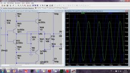
But first here something what bothers me, that difference between VFA and CFA. In my simulation everything looks very similar in both types just higher SR in CFA.
Here is simulation with voltage an current swing in the feeback node. For me it looks that voltage dominate.
BR Damir
Attachments
It's not cheating. It's called good engineering 🙂Richard, that's cheating 😉 You need to consider distortion of the various blocks in isolation, not after you have applied TMC or TPC. You should easily be able to get a VFA or MA to low levels on their own. After adding the OPS it goes up by 20 dB. All the small signal stages of course are fast and running in class A. It's that OPS that's the problem.
I DO consider the distortion of each stage .. but never in isolation. Investigating the dominant distortion mechanisms of each stage is what led me to the good performance in #1431 .. though this is really more a pointer to the potential available rather than a practical circuit.
Looking at distortion in isolation leads to my #1007 circuit .. which is no more or less sensible than the other circuits with perfect OPS .. except for much better performance 🙂
If I use Cherry or TMC, I consider the VAS + OPS as a single block. If I use JLH, Alex or MIC, then the IPS + VAS is a single block.
Both you and Damir have found recently that some topologies don't like advanced stuff like TMC, TPC, MIC, TPMIC or pure Cherry. If da blocks were independent, it shouldn't make any difference .. but they aren't.
I'll repeat my assertion that how the various 'blocks' interact and allow fancy compensation that encompass more than 1 'block' .. is perhaps their most important 'feature'.
Another approach is to look at either current or voltage at the 'input' to each 'block' to see if clean input gives clean output. If they don't (and they don't by a long shot) then it is even more silly to consider the blocks independent.
In my case, 'investigating the flat distortion spectrum of CFA', its the IPS/VAS interface which is responsible and the OPS distortion is only a small factor ... provided good compensation, eg TMC or Cherry is used.
At the end of the day, if an approach leads to better results, then its valid. After all, my heretical approach ends up at the same solution as your qx-Amp 😀
I'm hoping #1431, by showing the potential, inspires someone to do even
'better'.
'Better' is, as always, supa performance ... with less complexity.
- Home
- Amplifiers
- Solid State
- CFA Topology Audio Amplifiers