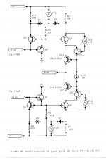
Example of one approach to class AB mirrors
The new voltage sources are adjusted to very slightly forward-bias the diodes. So when a fast transient occurs, they conduct and make the equivalent impedances in the mirror emitters much smaller, but they stay out-of-the-way for normal signals, except for a small capacitance variation and small forward current.Throwing in a wild card. The various mirror topologies can also be configured to operate in class AB, which allows good-sized resistive ballasting for lower input-referred noise, but reduces the required voltage headroom for pulsed currents.
Attachments
Thanks Antonio,
You are right, it's better without that resistor but not much(if it's value is higher bad influence is higher too, 1k does not change much). It was leftover from my pre amp project.
BR Damir
Dadod
I primarilly meant to at least look at the biasing of the following Q23/24 transistors. Seems like a trade betwen bootstrapped collectors and speed.
thanks
-Antonio
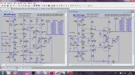
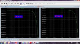
I tested two types of the CFA gain blocks in isolation and here are results.
First one is a current conveyour gain block with SR of 250V/usec and THD20k of 0.000004% at 60Vpp.
Secend one is standard CHA gain block with 137V/usec and THD20k of 0.000518% at 60Vpp.
Now it's time to resolve OPS problem. My HEC OPS is fast enough but with strange change in squre wave distortion, but latter about this.
BR Damir
Attachments
I tested two types of the CFA gain blocks in isolation and here are results.
First one is a current conveyour gain block with SR of 250V/usec and THD20k of 0.000004% at 60Vpp.
Secend one is standard CHA gain block with 137V/usec and THD20k of 0.000518% at 60Vpp.
Now it's time to resolve OPS problem. My HEC OPS is fast enough but with strange change in squre wave distortion, but latter about this.
BR Damir
🙂😎

The output stage is definitely the most critical. I've been getting some absurdly great sim results with a perfect output buffer. More parts than these, but defensible for achieving various goals, including very high power supply rejection (PSR). A recent mirror pushes the ballasting Rs to 2k, which means current noise at the inverting input will be low even with reasonably large feedback R, but bandwidth/slew rate remain high, with the class AB trick and a small compensation capacitor. But an output stage needs work.
It's interesting that Hawksford Error Correction (HEC) has basically not changed in all these years. I recall a slightly different version that used LEDs in an old Threshold schematic, and corrected for the use of DMOS output devices. One would think that there must be enhancements out there as well.
Note that I am trying to adhere to the suggestion of spelling out abbreviations, even though most following this know them already. I hunted down Bonsai's AFEC: Augmented Feedback Error Correction.
Hi,
Have You checked on noise? The 220k output-R will be noisy.
jauu
Calvin
Noise.
Attachments
Hi,
Have You checked on noise? The 220k output-R will be noisy.
jauu
Calvin
I Think that is to simulate the load of the output stage!? Correct dadod.
I Think that is to simulate the load of the output stage!? Correct dadod.
In some way, yes. It does not play any any role in the noise level, if I put any value here the noise level is the same. It defines loop gain width.
BR Damir
The feedback network is so low-resistance now that the contribution by inverting input current noise is small, although it could be further reduced with some lower-noise input current sources. But I calculate roughly 3nV/sq rt Hz output noise with the 200 ohm Rf, due to i sub n.In some way, yes. It does not play any any role in the noise level, if I put any value here the noise level is the same. It defines loop gain width.
BR Damir
For the voltage noise I believe it will be dominated at those operating currents by the rbb' of the input transistors. Does anyone know what those are for the BC550/BC560 parts? I tried to back a number out of the datasheet from On Semi for the 560, to find that the "typical" number is unbelievable, which is stated to be a noise figure of 0.5dB for 200uA Ic and a 2k source impedance. Just the "half-thermal" e sub n is worse than that, without accounting for any parallel noise.
Although they are popular parts I don't recall them being touted for low rbb'.
I really dont know the value.
You are correct about the feedback network. But with such low values you should be carefull not to do a step response on a real amp. With a step from 0 to 2vdc will generate a peak current in the diamond buffer of 200mA. That is a lot and it will destroy the transistors.
In general you should observe the peak current in the parts used when doing a step response.
With >100v/usec it is pretty high.
But with an input lowpass filter and audio signal it is not likely to happend.
rbb of bc550/560
Cordell-Modells.txt from Bob's website has rbb = RB = 167R for his BC550C and 170R for his BC560C ... which tie in with my own Jurassic noise measurements on similar small signal devices circa 1980.
His 'C' suffix denotes 'Cordell' rather than the high hfe classification.
PS I don't believe all of Bob's RB numbers but I think these are OK
0.5dB 2k NF @ 200uA Ic is not believable.Does anyone know what those are for the BC550/BC560 parts? I tried to back a number out of the datasheet from On Semi for the 560, to find that the "typical" number is unbelievable, which is stated to be a noise figure of 0.5dB for 200uA Ic and a 2k source impedance. Just the "half-thermal" e sub n is worse than that, without accounting for any parallel noise.
Cordell-Modells.txt from Bob's website has rbb = RB = 167R for his BC550C and 170R for his BC560C ... which tie in with my own Jurassic noise measurements on similar small signal devices circa 1980.
His 'C' suffix denotes 'Cordell' rather than the high hfe classification.
PS I don't believe all of Bob's RB numbers but I think these are OK

Woops I could swear this wasn't there when I looked yesterday 😱Although they are popular parts I don't recall them being touted for low rbb'.
See the bottom graph on page 3: http://www.onsemi.com/pub_link/Collateral/BC560C-D.PDF
I also blundered, and now feeding in beta and probable current noise and the approximate rbb' of 150 ohms, I get about their 0.5dB typical as being plausible for the stated conditions in the datasheet for the 560. I guess I started drinking wine a little early yesterday.
So, o.k. parts but, with these sorts of currents and impedances one could do better for voltage noise.
Yes see my post below yours, and above this one. Mea culpa. Still not the best parts for the app, but good enough.0.5dB 2k NF @ 200uA Ic is not believable.
Cordell-Modells.txt from Bob's website has rbb = RB = 167R for his BC550C and 170R for his BC560C ... which tie in with my own Jurassic noise measurements on similar small signal devices circa 1980.
His 'C' suffix denotes 'Cordell' rather than the high hfe classification.
PS I don't believe all of Bob's RB numbers but I think these are OK
rbb varying with Ic?
Any gurus want to comment on whether this actually happens?
Their fig 5. This is the first time I've seen rbb vary with IcSee the bottom graph on page 3: http://www.onsemi.com/pub_link/Collateral/BC560C-D.PDF
Any gurus want to comment on whether this actually happens?
ditto though its meths for dis beach bum! My facade as a pseudo guru is slipping 😱I also blundered, and now feeding in beta and probable current noise and the approximate rbb' of 150 ohms, I get about their 0.5dB typical as being plausible for the stated conditions in the datasheet for the 560. I guess I started drinking wine a little early yesterday.
I tested two types of the CFA gain blocks in isolation and here are results.
First one is a current conveyour gain block with SR of 250V/usec and THD20k of 0.000004% at 60Vpp.
Secend one is standard CHA gain block with 137V/usec and THD20k of 0.000518% at 60Vpp.
Now it's time to resolve OPS problem. My HEC OPS is fast enough but with strange change in squre wave distortion, but latter about this.
BR Damir
For now, you could try two approaches for the OP stage
ClassA
Sliding bias
I think HEC will still leave you with nonlinear input impedance.
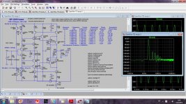
I doubled the feedback resistors values. With Rf=200 ohm it neads to be at least 5W.
Now I use for Rg 22 ohm and for Rf 470 ohm. SR goes down a bit, distortion goes down a bit too.
Noise is going up a bit.
BR Damir
p.s. phase margin is much better now, it will go down when ops inkluded
Now I use for Rg 22 ohm and for Rf 470 ohm. SR goes down a bit, distortion goes down a bit too.
Noise is going up a bit.
BR Damir
p.s. phase margin is much better now, it will go down when ops inkluded
Attachments
Last edited:
- Home
- Amplifiers
- Solid State
- CFA Topology Audio Amplifiers