Hello all,
I'd been working with vfa amps up until a year ago, honed the cfa using a positive and negative half and haven't looked back, the sonic results still have been not a smidgen less than steller. I also use an adaptive biased open loop output stage with Martin Logan esl panels, of course with an open loop output stAge they are a cinch to compensate under 10pf of lag which means wide ol bandwidth.
Colin
This is corroborated as well by people I know. If they were to publicize it more they would probably get less cooperation from reviewers.
Yes, I do not deny there may be a third view. Maybe even a fourth . . . 🙂
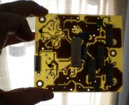
I'm working off and on stuffing a modest CFA using a fairly simple circuit with Exicon lateral outputs. I'm not playing any one-upmanship games re distortion and slew rate, but instead want to see if a relatively simple circuit can yield a listenable amplifier. I need to order some 100V E-line mosfets so I can finish stuffing the board. All the other components are in house. As a teaser, the picture shows the partially loaded board - single sided.
Attachments
I'm working off and on stuffing a modest CFA using a fairly simple circuit with Exicon lateral outputs. I'm not playing any one-upmanship games re distortion and slew rate, but instead want to see if a relatively simple circuit can yield a listenable amplifier. I need to order some 100V E-line mosfets so I can finish stuffing the board. All the other components are in house. As a teaser, the picture shows the partially loaded board - single sided.
Looks good. Can you share your circuit?
When I'm sure it works... The circuit is similar to the one I posted way, way back in this thread (post 308). One of several iffy things I'm trying is to see if I can get away with a simple pot + resistor arrangement to null the output offset. If this doesn't work I may have to bodge in a little board with an opamp servo.
Just placed the order for the fets. I'll have to match up pairs and glue each pair on a heat sink for both power dissipation and thermal tracking. I'm figuring either Arctic Silver or JB Weld might work equally well, given the fairly large thermal resistances. Both are loaded epoxies, though one is loaded with silver, and the other is loaded with steel.
One if by Ag, and two if by Fe.Just placed the order for the fets. I'll have to match up pairs and glue each pair on a heat sink for both power dissipation and thermal tracking. I'm figuring either Arctic Silver or JB Weld might work equally well, given the fairly large thermal resistances. Both are loaded epoxies, though one is loaded with silver, and the other is loaded with steel.
Running some numbers makes this conjecture seem less than promising, but the sign of the slope is reasonable. But something else I think is going on.It's indeed confusing. Fig. 5 most likely shows not the base spreading resistance, but the resistor equivalent noise. This is the sum of spreading resistance noise (bias independent) and the shot noise (decreases with Ic). Hence, the total equivalent noise resistance decreases with Ic.
I looked for Getreu but found Warner and Grung. Although undoubtedly a valuable tome, the index shows zero entries under noise. They probably explain this omission early on.
... 5 most likely shows not the base ... resistance, but the resistor equivalent noise....
Why do you say this?
The base resistance (Rbb) decrease is well documented.
The plot is clearly labelled resistance and not resistor equivalent noise.
The resistance decrease looks consistent with the known physics of the phenomenon.
Best wishes
David.
... Hawksford is of the 'obfuscate everything so da unwashed masses will be kept in the dark' school.
... at his paper for the last few days but its difficult ...
Yes, as I noted already, I read the paper repeatedly too before I started to see his point. Worth some effort.
Have you got some of the 2sa1316?
Yes. Only 30. I should have ordered more.
I've got a cryptic note in my handwriting that though these were the among lowest rbb devices I'd found, my own tests suggested they weren't quite rbb=2R.
The best devices I've tested between 0.5mA & 3mA (in da previous Millenium) were
Hitachi 2sa108x / 2sc545x range rbb=5R
Rohm 2sb737 about 2R and 2sd786 about 4R5
Absolute data at this level is difficult and I haven't tested yet.
A comparison I read put the Toshiba's a little better than the Hitachi's, in particular with low frequency noise.
I think Ovidiu Poppa tested the Hitachi's and found them about 2R.
This was for his low noise "CFA" phono pre-amp, just to stay on topic.
Best wishes
David
Last edited:
2SA1316, 2SC3329 I believe is intended.
Yes. Sorry for the typo.
... (BL bracket 350-700 at 2mA). rbb' is stated as 2 ohms typical at 1mA. They are not very fast parts compared to comparable ones with otherwise-similar characteristics , and at that only a single number is given for gain-bandwidth...
I can confirm the beta. Mine are all close to 375. Exactly in the middle of the bin overlap, which may be luck but is probably excellent process control.
I suspect they are just as fast as comparable parts. The one number quoted is at too low a current to reach max Ft. This looks like poor datasheet information rather than a slow part.
I have not confirmed this yet. What equipment do people here use to check Ft? Preferably cheaper than a network analyser😉
Best wishes
David
bcarso said:See the bottom graph on page 3: http://www.onsemi.com/pub_link/Collateral/BC560C-D.PDF
Their fig 5. This is the first time I've seen rbb vary with Ic
Waly, like Brad & Dave, I don't think this is total Rnv=rbb' + rnv where rnv is Shot Voltage Noise Resistance = 12R5/Ic Ic in mAWaly said:Fig. 5 most likely shows not the base spreading resistance, but the resistor equivalent noise. This is the sum of spreading resistance noise (bias independent) and the shot noise (decreases with Ic). Hence, the total equivalent noise resistance decreases with Ic.
If we take 3 pts on Fig 5 & subract rnv
0.1mA rb=170 : rbb'=170-125= 45R
1mA rb=159 : rbb'=159-12R5=146R5
10mA rb=130 : rbb'=130-1R25=128R75
.. which is a wild variation. It's likely the rb in Fig 5 wasn't determined by noise considerations but yus semiconductor gurus will have to tell us how its done.
The variation in Fig 5 from 130-170R from 0.1mA to 10mA (if it was rbb') would only give 0.6dB variation in SC noise at 0.1mA and 1.1dB at 10mA
I've found assuming a constant rbb' a good model for the LN transistors I've mentioned between 0.1mA to about 10mA and also for TI bc214/184/384 and Mullard/Philips bc109 which are closer to bc550/560
Baxandall WW78 says constant rbb' is a good assumption too. That article shows where this breaks down, mainly in frequency dependence (1/f & popcorn noise) ... and it affects rni (shot noise current resistance) more than rnv
Dave is right that Absolute data at this level is difficult. Your test jig ideally needs to have no evil resistors to obfuscate the issue 😉
VERY FEW applications can make full use of the potential LN performance of the best devices. Brad mentions the need to run the devices at high current but you soon reach a limit cos rbb' is actually part of your source resistance so at 3mA, rnv=4R2 so probably too low already. In fact I use the current beyond which there is no improvement as one of my reality checks on rbb'.
I didn't find any 1/f problems with the Hitachi devices. My test jig is also sorta CFA 🙂
For those who can't be bothered to read Baxandall, Shot Current Noise Resistance = 50R/Ic Ic in mA for a common base amp. For a common emitter amp, this is hfe times higher. This leads to an optimum source resistance (which must include rbb') of rt(hfe)/gm for common emitter and simply 1/gm for common base.
Jay Reed kindly sent me another list which included
Sanyo 2SC3504, 2SA1433
Sanyo 2SC3601, 2SA1407
as also having rbb' below 6R
Mr. Zan, I'd appreciate a hint on what to search on. Was it when I asked if there was a way to model the 1/f rise in Env & Inv?This is well documented. There are SPICE parameters to model this. RBM and IRB. I answered a question about this previously. The thread should be easy to find.
Last edited:
Mr. Zan, I'd appreciate a hint on what to search on. Was it when I asked if there was a way to model the 1/f rise in Env & Inv?
Didn't mean to be cryptic. A quick search of posts by Dave Zan with Rbb in the text turns up this
What-happens-bipolar-rbb-function-collector-current.html
In the thread I was a bit slow to remember the Spice details and had to check a reference to see what their symbol meant, but it's not too bad.
I understand it better now😉
Best wishes
David
jan.didden said:The best way to understand it is to trace base currents and to assume that all base currents are equal so if you sink one away from an Ie you have effectively compensated for that transistor's base current. And vice versa.
Du.uuh! I stil dun unnerstan dis base current re-cycling stuff. But just to show you don't have to be a pseudo guru to make good use of an effect, I'll point out that the simple circuit I show in #499 recycles the base current but in the opposite half of the amplifier to get the performance in #823. I didn't do it for da hi-falutin' re-cycling but cos I was hoping to get some extra Loop Gain. The distortion reduction was more than expected from the (negligible) increase in Loop Gain. Small but free cos its just moving a connection.... speaking of Baxandall, though I have yet to see it, Walt Jung said he found a followup in Baxandall's letter to the editor, about his initial Baxandall-Shallow article describing his "superpair", in which LTE he emphasizes the effective collector output capacitance reduction. Perhaps his explanation will be more straightforward of how Boxall's feedback compound transistors work to reduce distortion, than trying to reason it out from the Hawksford slope distortion paper, which I think mostly just deals with the Aldridge cascade circuit (the bootstrapped cascode that Hawksford thought he invented).
Doing the same thing to the symmetrical CFA in #825 drops THD 50W 8R to 6ppm .. not as good as Damir's 5.6ppm but with a slightly simpler circuit 🙂
THD remains 'flat' with frequency. I've another CFA variant where the THD profile is more like my VFA efforts. I'm not sure which approach is 'better'.
___________________________
Why is no one showering kudos on my #1007 circuit? 😡
Is it not complex enough to interest this august body? It's got better performance all round than the other suggestions with Unobtainium devices & perfect OPS. How about if I claimed all the parts are hand carved from solid Unobtainium by virgins? 🙂
Du.uuh! Excuse dis LTspice newbie hu dun know how to search 'posts by Dave Zan' 😡Didn't mean to be cryptic. A quick search of posts by Dave Zan with Rbb in the text turns up this
What-happens-bipolar-rbb-function-collector-current.html
My $0.02, which is shared by Baxandall, is that a constant rbb' seems to be a good assumption for noise. The frequency dependence of rnv & rni is more worrying.
Should be able to get a better handle on this by looking at noise contours. But usually, we are only interested in a very small part of the noise contours.
Simple Diamond IPS CFA with good performance?
I'm still looking for a Simple Diamond IPS CFA with good performance to help me understand this strange animal.
I've tried to sim Bonsai's nx-Amp but I'm getting THD near 1% which is MUCH worse than he measures.
Anyone have a LTspice *.ASC of the above animal?
Gotta be simple for someone like me with only 1 senile brain cell 🙂
Last edited:
Du.uuh! Excuse dis LTspice newbie hu dun know how to search 'posts by Dave Zan' 😡
Click on "Search" at the top of DIYAudio. Select "Advanced Search" This lets you search posts by a specific user and/or with more options for content.
Not related to LTSpice newbieness.
My $0.02, which is shared by Baxandall, is that a constant rbb' seems to be a good assumption for noise. The frequency dependence of rnv & rni is more worrying.
Should be able to get a better handle on this by looking at noise contours. But usually, we are only interested in a very small part of the noise contours.
I think constant Rbb for noise is fairly reasonable in practice. The Rbb only decreases much at current levels that inevitably decrease the Hfe too. Not usually where you want to run the transistor.
I have added flicker noise parameters to my 2SA1316 and 2SC3329 models and spot checks look about correct but I haven't worked out how to plot noise contours yet.
Best wishes
David
Ovidiu Poppa has a Diamond "CFA" phono pre-amp and an educational discussion. Check HPS 4.2
Ovidiu also checked those Sanyo transistors that you mentioned previously and found similar low Rbb.
There is a little info on the Sanyo fabrication process in one of their brochures but I have not been able to find more detail.
Last edited:
There is a little info on the Sanyo fabrication process in one of their brochures but I have not been able to find more detail.
http://home.arcor.de/thomasfetzer/Sanjo/SY103A_e.pdf page 7.
Polysilicon emitter, an insanely expensive technology to build discretes. Was mostly used for building very high frequency (and low noise) ICs. Currently obsoleted by other modern processes and methods. No wonder that Onsemi, rather than attempting to port these products to another modern process, dropped the whole FBET line.
Why do you say this?
The base resistance (Rbb) decrease is well documented.
The plot is clearly labelled resistance and not resistor equivalent noise.
The resistance decrease looks consistent with the known physics of the phenomenon.
Yes, but not by 25%. That's huge. For all practical purposes, Rbb can be considered constant, even if Spice has parameters to model a decrease.
I wouldn't care much about the plot labels. I've seen many such wrong labels, it's marketing people putting these together, errors often happen.
IF one would like to do some tinkering with this CFA topology and needed to purchase the BC550c type of transistors to tinker with, what brand and specific model number, quantity, and packaging as in bulk or ammo pack would be suggested? Both PnP and NpN, the higher the voltage the better for my high power needed speakers.
Thanks to all for this truly unique learning and drooling experience...😀
I can hardly wait to fire up the Tekscope, Keithly and Weller
Thanks to all for this truly unique learning and drooling experience...😀
I can hardly wait to fire up the Tekscope, Keithly and Weller
- Home
- Amplifiers
- Solid State
- CFA Topology Audio Amplifiers