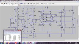
I simulated my current conveyor with Edmond Stuard non switching OPS(from Class i and siblings thread) and here is result.
THD20k is 18 ppm at 60 Vpp
This OPS is quite complicated and same or better result can be produced with much simpler OPS but I am not yet there.
BR Damir
THD20k is 18 ppm at 60 Vpp
This OPS is quite complicated and same or better result can be produced with much simpler OPS but I am not yet there.
BR Damir
Attachments
Hi Damir,
>This OPS is quite complicated and same or better result can be produced with much simpler OPS...
Yes, it's complicated. As for 'better results', do you mean lower THD? That's also correct. Notice that a sliding (and automatic) bias will always introduce more distortion compared to a non-sliding bias. You can't have it all. 🙁
BTW1, AB-II is intended for vertical MOSFET output sages. Results with BJT's are a bit less successful.
BTW2, Simulated THD20k of my latest design is below 1ppm. I think that's good enough. 😉
Cheers, E.
BTW2, Simulated THD20k of my latest design is below 1ppm. I think that's good enough. 😉
Cheers, E.
Hi, edmond, how much is the loop gain?
My amp is also less than half ppm, now it is pure feedback, without EC, XM, autobias, and only low biased class B.
I played with autobias and end up in XM. also playing with EC and ended with pure feedback.
I like pure huge loop. I could easily change its sound character, much easier compared to low feedback.
So what is the virdict on this promising idea?
BTW2 -- where is the schematic posted, pls? using what OPS/bias topology?
We still need a low/near zero distortion OPS for the CFA.
Thx-RNMarsh
BTW2 -- where is the schematic posted, pls? using what OPS/bias topology?
We still need a low/near zero distortion OPS for the CFA.
Thx-RNMarsh
Last edited:
Hi Damir,
>This OPS is quite complicated and same or better result can be produced with much simpler OPS...
BTW1, AB-II is intended for vertical MOSFET output sages. Results with BJT's are a bit less successful.
BTW2, Simulated THD20k of my latest design is below 1ppm. I think that's good enough. 😉
Cheers, E.
Yes I know Edmond that is valid when used in a VFA amp, but here were search for a propriety OPS suitable to be used in a CFA amp.
BR Damir
Now now, Mr. O'Connor. No aspersions on that fine academic body, the Institute of Electrical & Electronic Engineers. 😀Yet, some publishers will print anything that is sufficiently burdened with math as to flummox most readers. Those who wade through realise what they've swam through...
PS: To those who wish to have their words of wisdom in IEEE Trans., be warned you need to start with Triple Integrals and go up in level from there if you want to be in with a chance. But don't worry. At this level NONE of your referees will bother (or be competent) to check your maths 🙂
Another useful tip is to have Babelfish translate your paper to French and then back again to add extra polysyllabic pontification. German is not nearly as good for this.
Not to pour oil to the fire, but I think it's interesting that also this discussion ended up at the dreaded output stage =)
What's the 'best' parameter to get an OPS under control? Previous stage's linearity? Or is is global feedback? Loopgain?
What's the 'best' parameter to get an OPS under control? Previous stage's linearity? Or is is global feedback? Loopgain?
Not to pour oil to the fire, but I think it's interesting that also this discussion ended up at the dreaded output stage =)
What's the 'best' parameter to get an OPS under control? Previous stage's linearity? Or is is global feedback? Loopgain?
Or local feedback (error correction) around the OPS.
One thought (thinking out aloud) is to use something like Bonsai's AFEC around the output stage.
It would be more logic to *begin* with the OPS, as it is the main contributor in distortion (~1%).Not to pour oil to the fire, but I think it's interesting that also this discussion ended up at the dreaded output stage =)
What's the 'best' parameter to get an OPS under control? Previous stage's linearity? Or is is global feedback? Loopgain?
And there, i see only two tracks: error correction (Cordell like) or Elvee like error cancellation (http://electronicdesign.com/Content/14978/60028_fig.gif).
For the moment, all the tries with input stage had brought-me to a negative conclusion: Lot of complexity, too much slew-rate and bandwidth impact (that's not what we want with CFA, did-we ?) for few improvements in the global HD.
And at the end, the question will be: "Did we really need all this ?" .
I mean, when a simple VSSA sims at <0.001% at 1Kz ?
My personal amp, similar, but with a cascoded VAS giving similar results.
Mr Marsh will soon be able to listen to a VSSA and answer this question on the only point of view that matters, the subjective one given by his ears 🙂
Is the problem the 10KHz distortion ? Ok, let's try to extend the open loop bandwidth with the same gain. ;-)
Another catch up.
They are even better than that. The default RB is not 10R, it's zero🙄
I don't believe RB is usually determined from noise measurements.
There are some issues here that I haven't sorted out. I think Bob Cordell discussed this once?
Thank you for the recommendation but too bulky and more expensive than I want. Just a quiet mic pre-amp.
Thanks for the reminder. I remember the "Mitey Mike" made from these. Fits the requirement but I have too much to build already. I just want to BUY for once.
And thanks for the reference. The local library has this. I will check it soon.
Best wishes
David
...
Be careful of RB in SPICE models. It dun usually reflect rbb for noise. The default value is RB=10R. Pity Mouser & Digikey are out of stock of the default LTspice NPN & PNP devices 🙂...
They are even better than that. The default RB is not 10R, it's zero🙄
It's a difficult measurement to make, but I suppose they may have gotten a few points and then drew the curve through them. At the highest currents, a pulsed measurement of noise in a well-defined narrow bandwidth at high frequencies could be done before dissipation had heated the device very much.
I don't believe RB is usually determined from noise measurements.
There are some issues here that I haven't sorted out. I think Bob Cordell discussed this once?
I am using the ECM8000 with a Terratec DMX 6Fire USB which provides a XLR Mic input and is capable to deliver 48V phantom voltage too. The output quality of this USB sound device is also good enough for most measurements.
Software: ARTA
Thank you for the recommendation but too bulky and more expensive than I want. Just a quiet mic pre-amp.
Thanks for the reminder. I remember the "Mitey Mike" made from these. Fits the requirement but I have too much to build already. I just want to BUY for once.
There is an excellent discussion in Sze and Ng, Physics of Semiconductor Devices 3rd ed., not restricted to ICs per se, and including many equations and ample drawings of the devices...
And thanks for the reference. The local library has this. I will check it soon.
Best wishes
David
Yes I know Edmond that is valid when used in a VFA amp, but here were search for a propriety OPS suitable to be used in a CFA amp.
BR Damir
Hi Damir,
Maybe I'm overlooking something, but I don't see why this OPS is incompatible with a CFA front-end. Any hint?
Cheers, E.
Hi Damir,
Maybe I'm overlooking something, but I don't see why this OPS is incompatible with a CFA front-end. Any hint?
Cheers, E.
Hi Edmond,
I simulated two type input gain block, one is current conveyor type, other is more standard gain block, suitable for CFA, look here http://www.diyaudio.com/forums/solid-state/240712-cfa-topology-audio-amplifiers-107.html#post3630704. Both gain blocks with quite low distortion in isolation, particularly the current conveyor type.
I tried different OPS and every time distortion increase was quite high. It looks like both type of the gain blocks are very sensitive to a load(nonlinear one I suppose, as simple resistor did not increase distortion just lowered the gain). Even with your AB2 OPS increase of distortion was higher then with some of simpler OPS. One have to take in account lower gain(or loop gain) of the gain blocks, so level of the feedback is lower then standardly used in VFA amps.
In may GainWire thread I simulated influence of the OPS(od output buffer) on distortion. GainWire is non global negative feedback pre amp and it's possible to follow how distortion was increased on the gain block output when output buffer was connected. By simulation in that way I choose the output buffer with lowest distortion increase(of course with low own distortion too).
Best regards Damir
P.S.of course one can take completely differen design approach, and make much simpler CFA if satisfied with higher distortion, but here for me it's technical challenge to design with lowes possible distortion
Last edited:
A good option here might be to put an IC error correction circuit around the output stage similar to Jan Didden's PAX amplifier. Ideally, you want the input to the output stage to be the + input of the opamp (I suggest a video op amp for the wide bandwidth and minimum phase shift).
It's easy to float the error correction amp ( use a 5 V device) and I tried this in LTspice a few years ago ( and posted it up on the forum) with good results.
This will give you your high input impedance, low distortion output stage.
It's easy to float the error correction amp ( use a 5 V device) and I tried this in LTspice a few years ago ( and posted it up on the forum) with good results.
This will give you your high input impedance, low distortion output stage.
Dadod, oh, please, don't feel my words like a critic.P.S.of course one can take completely differen design approach, and make much simpler CFA if satisfied with higher distortion, but here for me it's technical challenge to design with lowes possible distortion
Your work on this CFA study is VERY interesting and educational. And i'm personally very thankful you share-it. Anyway, how to chose the best way without knowing all of them ?
Just i wanted to make remember that amplifiers are for sound reproduction, and numbers don't always correlate with real behavior and listening impressions ;-)
And to insist on one point, to take the stupid car comparison: we can't design with the same criteria limousines and race cars, see what i mean ?
The first thing i look at, when i work on CFAs is square waves, while the first thing with VFA is, indeed, H.D..
The entirety of chapter 5 is worthwhile. The material about current crowding starts on page 261.And thanks for the reference. The local library has this. I will check it soon.
Best wishes
David
I'm glad I have the earlier editions, as a good deal of stuff has since been deleted. Ditto Gray and Meyer editions.
It would be more logic to *begin* with the OPS, as it is the main contributor in distortion (~1%).
And there, i see only two tracks: error correction (Cordell like) or Elvee like error cancellation (http://electronicdesign.com/Content/14978/60028_fig.gif).
For the moment, all the tries with input stage had brought-me to a negative conclusion: Lot of complexity, too much slew-rate and bandwidth impact (that's not what we want with CFA, did-we ?) for few improvements in the global HD.
And at the end, the question will be: "Did we really need all this ?" .
I mean, when a simple VSSA sims at <0.001% at 1Kz ?
My personal amp, similar, but with a cascoded VAS giving similar results.
Mr Marsh will soon be able to listen to a VSSA and answer this question on the only point of view that matters, the subjective one given by his ears 🙂
Is the problem the 10KHz distortion ? Ok, let's try to extend the open loop bandwidth with the same gain. ;-)
My main performance yardstick for real amplifiers is 20kHz THD measured in a 200kHz bandwidth (unfortunately many THD analyzer measurements are done only in an 80kHz bandwidth). Ultra-low 1kHz THD measurements are of limited interest to me. Also, in a real amplifier, do not overlook 50Hz THD; there can sometimes be a surprise there.
Bear in mind that increasing open-loop bandwidth without increasing ULGF will often not improve THD20 with conventional Miller compensation. If one achieves higher feedback factor at 20kHz by using TPC or TMC, for example, then improvement in THD20 can be expected.
Cheers,
Bob
Output Stages
One remark: the relatively low-power output stage shown by linuxguru and modified later (see http://www.diyaudio.com/forums/digital-source/239597-linuxguru-buffer-redux-beyond.html) with performance improvements, can be readily enlarged into a very-high-performance higher-power version. In the most straightforward case it is pure class A, which of course is quite extravagant for power consumption and needed heatsinking. But the performance looks outstanding, and such that I wouldn't bother trying to close a larger loop around it, other than possibly a d.c. servo.
There are ways to add some current-boosting circuits to make the resulting combination operate in class AB. It's not clear how much the standing current in the "pure" buffer can be reduced before performance begins to suffer enough to preclude further standby power reduction.
So if either a voltage-feedback or current-feedback basic amp is pursued, the amp should have enough capability to supply a stiffish feedback divider, and then the buffer appended to drive the main load. It's possible for a much simpler output stage for the main amp to have sufficient performance, particularly as the loading of the feedback network is well-determined and its loading readily compensated. So there is still an output stage "problem", but a much easier one to solve.
Last edited:
Yes, Bob.Bear in mind that increasing open-loop bandwidth without increasing ULGF will often not improve THD20 with conventional Miller compensation.
Let's take a typical CFA example, where we don't use Miller caps, or just to kill a peak in the response curve around 10MHz. The main pole is most often fixed by the feedback impedance.
I believe in two things we then have to balance.
If we improve the open loop bandwidth, Cascoding the VAS, for instance, we will decrease the phase error between signal and feedback at 20KHz. Then, get a more efficient 'error correction' at high frequency or, if we prefer, a better feedback ratio.
In the same time, we will be able to decrease the feedback impedance keeping the same stability margin, (thas means increase of the ULGF) thus have less distortion with the non linear emitter parasitic capacitance .
Am-i wrong ?
If we were able to have an open loop bandwidth flat up to 200KHz, we should had a flat distortion curve up to 20KHz.
Distortion at 50Hz often occurs for the same reason (if PSU is perfect). When a cap had been added in the feedback loop, to help DC offset, introducing phase errors between signal and feedback at low frequencies. It happens in VSSA, with the caps shunting the CCS to ground for AC.
It seems ridiculous, but our 100MHz devices are not yet fast enough to reproduce perfectly a 20KHz signal in a closed loop system. ;-)
Unless, as you say, complicated games with some TPC and local feedbacks to reduce those global open loop phase errors at the upper audio frequencies.
Last edited:
🙂😎
Thats right -- its exactly what I get too. Flat thd without the heartburn of stability/comp/phase margins vs neg feedback and more limited OL-BW.
The idea of using more and ever more gnfb is fine for reducing distortion etal.... until you reach the higher audio freqs and it becomes harder to get and keep everything stable.
The discussions about compensation techniques show this is a practical limiting factor to the high feedback design approach. might not be for circuits that do not need or wish to attain the lowest possible thd/harmonics at 20KHz/full power etc... It just starts getting harder to get lower thd at high freqs and keep it stable when the freqs are within the bandpass of the signal being amp'ed...... compensation far away in freqs is better in many ways and quit practicle and simple. more later... .
Thx-RNMarsh
If we were able to have an open loop bandwidth flat up to 200KHz, we should have a flat distortion curve up to 20KHz.
Thats right --
its exactly what I get too. Flat thd without the heartburn of stability/comp/phase margins vs neg feedback and more limited OL-BW. The idea of using more and ever more gnfb is fine for reducing distortion etal.... until you reach the higher audio freqs and it becomes harder to get and keep everything stable.
The discussions about compensation techniques show this is a practical limiting factor to the high feedback design approach. might not be for circuits that do not need or wish to attain the lowest possible thd/harmonics at 20KHz/full power etc... It just starts getting harder to get lower thd at high freqs and keep it stable when the freqs are within the bandpass of the signal being amp'ed...... compensation far away in freqs is better in many ways and quit practicle and simple. more later... .
Thx-RNMarsh
Last edited:
This OPS is quite complicated and same or better result can be produced with much simpler OPS but I am not yet there.
BR Damir
I think it is a very good approach/attitude.... once gone this far, it is easier to simplify because you have a better understanding of what is now really needed to make it work best and what isnt and how to do a better work-around. You have a good approach to solving the problems.
THX-RNMarsh
Last edited:
- Home
- Amplifiers
- Solid State
- CFA Topology Audio Amplifiers