Noise in Current Mirrors
Until Brad returns - Read this Link from Samuel. Excellent comments about noise towards the front.
Best wishes
David
Then please...
Until Brad returns - Read this Link from Samuel. Excellent comments about noise towards the front.
Best wishes
David
Heh, yes, I was just looking at one of the references I suggested to Samuel.Until Brad returns - Read this Link from Samuel. Excellent comments about noise towards the front.
Best wishes
David
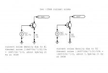
Waldhauer, in his excellent book Feedback, after analyzing the unballasted mirror, writes: "Figure 11.6a shows a way to quiet the current mirror by adding equal resistors in series with the diode and the transistor emitter. On the surface it seems paradoxical that we can quiet the current mirror by adding resistors that are themselves noisy..." [my italics].
Attached are a couple of examples to show the effect.
As far as the amplification of noise in the input current signals, mirrors are mirrors, and will pass that noise to the output, ideally unchanged.
Attachments

IPS & VAS for jan.didden
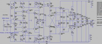
This is actually for Mr. Didden who would have us compare IPS & VAS with 'ideal' OPSs .. with apologies to Belaji & also Guru bcarso.
It in fact has less Unobtanium parts than Belaji's #856 circuit and half its THD at 20kHz 50W 8R. I added a 8R load which he left out. 🙂
The THD is almost pure 2nd for yus Golden Pinnae but at such a low level that its academic.(????) Other products are below 10 ppb.
Models are standard Cordell & LTspice.
You can see its slighly simpler than Belaji's ... and I would have it even simpler but then I couldn't claim its a CFA.
______________
I stand by my assertion that you can't look at dis stuff in isolation. How the IPS/VAS interfaces with the OPS is probably its most important feature.
Attachments
There has been a lot written on this subject and it does seem paradoxical.
In a practical amplifier, and especially one where the input current is quite high (mA rather than uA) the resistor value is unfortunately limited by practical considerations. In a practical power amplifier however, you can for the most part get away with it, except of course where you may be driving very efficient speakers.
In a practical amplifier, and especially one where the input current is quite high (mA rather than uA) the resistor value is unfortunately limited by practical considerations. In a practical power amplifier however, you can for the most part get away with it, except of course where you may be driving very efficient speakers.
Some more sim work I completed last night.
I have added Brad's latest design - we are down to ~2.5ppm at 50V pk to pk at 20 kHz. However, variant one that I posted up yesterday is now at 700 ppb for the same input and output signal conditions.
Loop gains and closed loop bandwidths are almost identical.
I've used 'Alexander' comp for these sims.
Attachments
Heh, yes, I was just looking at one of the references I suggested to Samuel.
Waldhauer, in his excellent book Feedback, after analyzing the unballasted mirror, writes: "Figure 11.6a shows a way to quiet the current mirror by adding equal resistors in series with the diode and the transistor emitter. On the surface it seems paradoxical that we can quiet the current mirror by adding resistors that are themselves noisy..." [my italics].
Attached are a couple of examples to show the effect.
As far as the amplification of noise in the input current signals, mirrors are mirrors, and will pass that noise to the output, ideally unchanged.
I had the pleasure of working with Fred Waldhauer at Bell Labs in the early 1970's. I still remember his excitement in describing many feedback systems with ABCD parameters. He also designed a gigahertz op amp in the 1970s.
He was a brilliant character.
During that time he led the development of key functions in the T4M digital coaxial transmission system, operating at 274 Mb/s circa 1974.
He went on to do some pioneering work in hearing aids.
Cheers,
Bob
Heh, yes, I was just looking at one of the references I suggested to Samuel.
Waldhauer, in his excellent book Feedback, after analyzing the unballasted mirror, writes: "Figure 11.6a shows a way to quiet the current mirror by adding equal resistors in series with the diode and the transistor emitter. On the surface it seems paradoxical that we can quiet the current mirror by adding resistors that are themselves noisy..." [my italics].
Attached are a couple of examples to show the effect.
As far as the amplification of noise in the input current signals, mirrors are mirrors, and will pass that noise to the output, ideally unchanged.
Thanks for the analyze.
Some more sim work I completed last night.
I have added Brad's latest design - we are down to ~2.5ppm at 50V pk to pk at 20 kHz. However, variant one that I posted up yesterday is now at 700 ppb for the same input and output signal conditions.
Loop gains and closed loop bandwidths are almost identical.
I've used 'Alexander' comp for these sims.
Some practical values.
If you do not use matched pair like BCM847BS and BCM857BS the value of 33R will give you an large imbalance in the current transfer as you easily can have 10mV or more difference on the VBE voltage creating an imbalance of at least 330uA. This offset will affect the system initial DC offset.
In circuit 1 you have C2 and C3 across R3 and R4. It is good to speed up the slewrate and raise the openloop gain, but an 1mF capacitor will have its resonance point below 1MHz in real life. And we try to make an an with high bandwidth.
Sorry .. It is not to be harsh, but that is my experience.
Sonya this is a sim - in a practical design of course you will need to match the devices, or used matched pairs as you note.
For the LHS configuration, the front end is designed to mitigate the DC balance issues. However, cap performance is important I agree. Note, I used the models for the caps from the library.
For the LHS configuration, the front end is designed to mitigate the DC balance issues. However, cap performance is important I agree. Note, I used the models for the caps from the library.
High power version.
THD20k
8 ohm 140W 5.13ppm
4 ohm 277W 4.66ppm
3 ohm 340W 6.28ppm
THD1k distortion around 1ppm for 4 and 8 ohm load at same power level.
BR Damir
THD20k
8 ohm 140W 5.13ppm
4 ohm 277W 4.66ppm
3 ohm 340W 6.28ppm
THD1k distortion around 1ppm for 4 and 8 ohm load at same power level.
BR Damir
Attachments
Sonya this is a sim - in a practical design of course you will need to match the devices, or used matched pairs as you note.
For the LHS configuration, the front end is designed to mitigate the DC balance issues. However, cap performance is important I agree. Note, I used the models for the caps from the library.

No problem. for the diamond buffer. the 4 resistors used can easily be 4.7 - 10R.
With a constant current source,all 4 transistor placed close together.
the offset voltage und current is constant. close to 0mV offset on the diamond buffer, and in the same time, close to a perfect buffer, as you only have a 5 - 15Ohm output impedance of the buffer with an bias current of 2 - 5mA
dadod, whats the bandwidth and SR look like? You could drop your F/back resistors by 10x and see what you get.
No problem. for the diamond buffer. the 4 resistors used can easily be 4.7 - 10R.
With a constant current source,all 4 transistor placed close together.
the offset voltage und current is constant. close to 0mV offset on the diamond buffer, and in the same time, close to a perfect buffer, as you only have a 5 - 15Ohm output impedance of the buffer with an bias current of 2 - 5mA
Yes, the thermal stability of the front end stage is quite good I have found - once the offset is trimmed, it stays at 1-2mV at the amp output.
I've done a bit more tweaking on the 3 TIS stages I posted earlier today and the LHS variant is at 390 PPB and the two RHS versions are at 1 ppm.
But, they are complex IMV . . .
But, they are complex IMV . . .
amplifier with the local current negative feedback in the driver without the general negative feedback, as well as negative output resistance of approximately minus 0.25 Ohm
amp_negative_out_resistance.zip
best regards
Petr
amp_negative_out_resistance.zip
best regards
Petr
dadod, whats the bandwidth and SR look like? You could drop your F/back resistors by 10x and see what you get.
If I go below 100/2.2k for feedback resistors I've got much worst PHM and GM and I did not succseed to get there changing compensation or CCS current.
With 100/2.2k I have to increment shunt cap (C5) from 150p to 220p to get the same PHM and GM of 11dB and THD20k droped from 5.13ppm to 2.81ppm for 140W on 8 ohm.
Last edited:
Hi Kgrlee
The 8 Ohm load resistor I left out is because of the perfect VCVS. It laughs at any load!
Bela
The 8 Ohm load resistor I left out is because of the perfect VCVS. It laughs at any load!
Bela
If I go below 100/2.2k for feedback resistors I've got much worst PHM and GM and I did not succseed to get there changing compensation or CCS current.
With 100/2.2k I have to increment shunt cap (C5) from 150p to 220p to get the same PHM and GM of 11dB and THD20k droped from 5.13ppm to 2.81ppm for 140W on 8 ohm.
FFT at 1W on 8 ohm.
Noise is 58nV/Hz1
Attachments

- Home
- Amplifiers
- Solid State
- CFA Topology Audio Amplifiers