Further, since you could use the TIS load resistor to define the loop gain, the adjustment range could indeed be made from 0dB through to 50 or 60 dB so you could in theory go from ZGNF to High global feedback by simply adjusting a potentiometer.
This needs to be done and listened to it under various gnfb levels.
Thx-RNMarsh
The room is not small. I sit between 3 and 4 metres from the speakers so 11 dB down from 1 m sensitivity.
That make 86 dB / W. So 106 dB peak means 100 W into 4 ohms. Spot on.
I plan 600 W so I should have plenty of headroom.
Best wishes
David
For the 'typical' room size and typical efficiency speakers used today..... an amp power level needs to be established here for a CFA PA design target level. [use EIA, AES, BBC, et al room size standard]
What would be that power level (range) for design?
Thx-RNMarsh
Last edited:
Does it not also depend upon the dynamic range of the listening material? What is a good "average" value to assume? And also what percentage of clipping is assumed?
Kgrlee,
" A small speaker may have good bass .. but then it needs the 1000W amp
 "
"
You got that right! I have a 6 1/2" that has an fs of 35hz and you can imagine the power required to reach high spl levels. Helps that it has 1" p to p excursion.Under-hung coil in a long gap magnet system.
" A small speaker may have good bass .. but then it needs the 1000W amp
You got that right! I have a 6 1/2" that has an fs of 35hz and you can imagine the power required to reach high spl levels. Helps that it has 1" p to p excursion.Under-hung coil in a long gap magnet system.
This needs to be done and listened to it under various gnfb levels.
Thx-RNMarsh
That's the idea! Workin' on it!
An example within of a JFET-DMOS current mirror
http://www.diyaudio.com/forums/digital-source/217057-inverting-current-conveyor-approach.html
Note the N-channel current mirror within the overall circuit.
The corresponding P-channel mirror would as usual be poorer performance. With ideal matching of the BF862s this looked awfully decent, although I forget the exact predicted performance. The photovoltaic optos are a bit large. Since no current to speak of flows in the gates, primary batteries will last their shelf life, although if you are like me you'll be fretting that they are slowly changing.
Hi Guys
Just a thought for the guys who want huge head room to avoid clipping: add class-C rail boosts, ie, make a CFA amp that is class-G.
Design the main part of the amp to handle day-to-day levels, and modern compressed music without transitioning to the upper rails. If the transients on the dynamic music are short enough and loud enough, the distortion added because of the transition should be masked.
Have fun
Kevin O'Connor
Hmm then then the unavoidable question arises.. what would be a good opamp to drive 100R input impedance at low signal levels? (2Vpp max)? Too bad I don't have a model for the AD826, but from using it in Multisim, it did well for the function.
But, from what you derive the 1K feedback resistance? In unity gain the output would go straight to the - input without a feedback resistor.
Edit: I tried the LT1152 audio opamp but then I need to parallel at least 3 of them to keep the distortion lower than that of the amp itself.
Also, it wouldn't matter much if I increase the amp feedback network by 3.3 to get an input resistance of 330R.
you missed a basic point of CFA - the feedback R controls the compensation
CFA always have to have the feedback R - it has to be sized for stability == bigger for lower gain
even 2 K Rf could be used with LT1229 for unity gain to "overcompensate" for more Cload margin
note that the datasheet graphs lowest gain is Av +2
the feedback R can be bypassed with an inductor - in Spice - trying to find a real inductor behaving like > 1 kOhm for a wide enough frequency range around 100 MHz is going to be a challenge
LT1469 is a "single stage" VFA, shouldn't hurt your distortion performance as a buffer - just a bit light on the output drive with 15 mA worst case min though so may not take full Class A output pull down
OPA827 is fet input so may match higher Z volume pot better, has much higher current drive spec
Last edited:
the feedback R can be bypassed with an inductor - in Spice - trying to find a real inductor behaving like > 1 kOhm for a wide enough frequency range around 100 MHz is going to be a challenge
Have you tried? Sort of like the JE990 but more extreme.
in Spice, yes - in the real world, no
I don't know of any inductor I'd trust to >100 Mhz for > | 1 kOhm | Z - maybe some lossy ferrite bead cores?
the Z has to be up there for a few octaves around the unity loop gain intercept to not wipe out stability margins
my use of CFA as output buffer/gain stage in composite op amps gives the noise of the input op amp - any unity gain CFA feedback I_n*Rf noise is servoed out to way beyond audio
trying to find a real inductor behaving like > 1 kOhm for a wide enough frequency range around 100 MHz is going to be a challenge
Not really. Self resonates at 600MHz (with about 1.7pF parasitic capacitance), at 100MHz should be a pretty good 1k inductive.
not saying its impossible - just that model errors, board parasitic make it uncertain
using 2x in series of the highest Z bead model in LTspice with a 1 pF pad to plane C guesstimate
sim shows only 48 degrees phase margin - again not hopeless but don't try this at home without a 200+ MHz 'scope
using 2x in series of the highest Z bead model in LTspice with a 1 pF pad to plane C guesstimate
sim shows only 48 degrees phase margin - again not hopeless but don't try this at home without a 200+ MHz 'scope
Attachments
Last edited:
Gedankenblitz
I thought about this some more and finally realized what is now obvious to me: the higher current noise is due to the mirrors, primarily, since there is no current gain at the input emitters. And the only way I can see to make lower current noise mirrors is by using bigger emitter (or source) ballasting resistors, which eats up a lot of volts. Now for power amplifiers this may not be such a limitation, as we can use auxiliary rails. But the measures needed to achieve a serious reduction are pretty intense. I'm looking at a mirror design with 10k ballasting R's that manages a 19MHz 3dB point when loaded with compensation caps, and since in a symmetrical design there will be one above and one below contributing, I see an input referred noise of about 2.6pA/sq rt Hz, which is in LME49990 (a VFA) territory. Not bad, but e sub n won't be quite as good as envisioned. although it will be less than probable other contributions to overall noise. Still in all probably o.k. for a power amplifier. The aux rails need to be about 15V larger in magnitude than the main rails for the input quiescent currents.G
It bothered me that Ramus in the TI piece says that "the inverting input current noise is always much higher than VFB equivalents". Although this seems intuitively plausible --- certainly there's more current flowing in those emitters --- I'm not fully persuaded that it is a fundamental limitation for bipolar CFA versus bipolar VFA. I think the issue is obscured by other circuit details. So I've been looking at the problem and came up with some approaches that seem to pan out.
mirror stability
A while back I found to my chagrin that with fast-enough transistors, it appears that the good old Wilson mirror will be oscillatory. I suppose it shouldn't be that surprising, as it is a feedback amplifier of sorts.
A while back I found to my chagrin that with fast-enough transistors, it appears that the good old Wilson mirror will be oscillatory. I suppose it shouldn't be that surprising, as it is a feedback amplifier of sorts.
Thanks for that info Brad.
I have not used this configuration in a practical amp - only sims - but I've heard about the stability issues.
Ultimate mirror as used in latest generation CFA opamps and used in the gainwire design. Its patented but its DIY. Not necessary in a typical CFA amp but good if youre planning NGFB. All mirrors display peaking, this one is more prone but nothing some compensation cant cure.
Attachments
A while back I found to my chagrin that with fast-enough transistors, it appears that the good old Wilson mirror will be oscillatory. I suppose it shouldn't be that surprising, as it is a feedback amplifier of sorts.
All mirrors except the basic one shows a measure of peaking, the Wilson is about the most troublesome one.
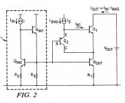
A Boxall stuck on to the output of a fairly standard mirror. Oh well, no patent will surprise me anymore 🙄Ultimate mirror as used in latest generation CFA opamps and used in the gainwire design. Its patented but its DIY. Not necessary in a typical CFA amp but good if youre planning NGFB. All mirrors display peaking, this one is more prone but nothing some compensation cant cure.
I wanted to use a little known advantage of CFAs .. that they can be designed to have much lower input noise than an equivalent VFA 🙂
Very sensitive speakers will hiss at you even with nothing playing.
This was not my experience with the e-JMLC horn driven (below) by a 650 W Chevin amplifier. Ear just at the mouth, there was only a very light buzz.
An externally hosted image should be here but it was not working when we last tested it.
There are many freaks of high efficiency systems (medium and tweeter horn based) in France, maybe a bit more than other parts of the world. The bass driver is generally bass-reflex loaded with a nominal sensitivity around 96 dB SPL/2.83V/1 m or more.forr, I'd very much like to know your 96dB/2.83V @ 1m speakers.
Reading threads about Jean-Michel Le Cleach's horns will probably lead you to many examples of full high efficiency systems.
I find horns inappropriate for domestic listening at 3 - 4 meters or less.
My system is based on direct drivers, 18 cm ScanSpeak Revelator (sensitivity 85.5 dB, used in range 160 Hz - 2 kHz) and 28 mm ScanSpeak (sens. 90 dB). My listening position is at 2 m from the loudspeakers.
The highest peak voltage I measured across the voice coil of the Revelator is 7 Vpk. The amps are driven by a digital processor with a maximal output around 10 Vpk FSD. There is an attenuator of 30 dB ahead of the amps, so their voltage peak input can never be higher than 0.35 Vpk. The amps having a voltage gain of 20 (26 dB), the output never goes beyond 7 Vpk.
My amps can deliver 20 Vpk (14 Vrms, 25 W in 8 Ohm), so there is a large margin before overload. I made them very small, they do not need huge power supplies or heatsinks (they never become warm except when tested at the laboratory stage). They are Renardson's circuits and they do not deliver the slightest buzz or hiss when the ear is in very proximity of the cone.
I do not mean this is a typical system, I just want to demonstrate that it is quite easy to correctly size the elements of an audio system for an intended SPL in a manner to avoid any clipping at the amp stage.
A Boxall stuck on to the output of a fairly standard mirror. Oh well, no patent will surprise me anymore 🙄
Indeed, the standard mirror being a EF augmented one, its clever. This patent is fairly recent suggesting no one thought of combining these mirrors before. A member here stumbled on the idea by himself. This is part of texas very low THD CFA range of opamps. Its unstable and displays large amounts of peaking but curable.
- Home
- Amplifiers
- Solid State
- CFA Topology Audio Amplifiers