stray capacitance
Hi David,
The SuperTIS is only extreme sensitive to nonlinear capacitances, like Cob. Therefore the collectors of the next stage should be bootstrapped. Loading the TIS output with (linear) 20pF and 500kOhms for example has hardly any effect. THD20k rises from 0.65 to 0.74ppb. Besides, stray capacitances are easily avoided/neutralized by using guard rings or planes on the PCB.
Cheers,
E.
Current Mirrors can be OK, just not combined with a beta enhancer.
Edmond's SuperTIS has no current gain at all but very sensitive to stray capacitance and the like.
[..]
Best wishes
David
Hi David,
The SuperTIS is only extreme sensitive to nonlinear capacitances, like Cob. Therefore the collectors of the next stage should be bootstrapped. Loading the TIS output with (linear) 20pF and 500kOhms for example has hardly any effect. THD20k rises from 0.65 to 0.74ppb. Besides, stray capacitances are easily avoided/neutralized by using guard rings or planes on the PCB.
Cheers,
E.
since some insist on comparisons - how about the same output Q, output bias as Esperado's VSSA CFA example
but with the LTP actually designed as today's standard - still just adding 2 Q to turn the CFA example into VFA, otherwise same number of ccs, compensation components - arranged differently
essentially same phase margin
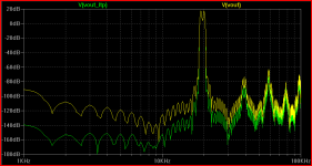
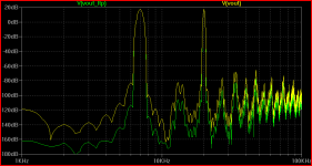
but lots more loop gain at audio, lots lower distortion - illustrated with 2-tone IMD FFT
on the slew rate front - the VFA modulates the input Q ~ 16 uApp max on the 19+20 kHz
while the CFA needs 150 uA - good thing its "inherently more linear" - it has to be
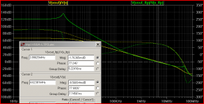
looks like green *_ltp beats yellow cfa example in 2-tone distortion fft - especially in the in band IMD:
(same VSSA circuit, same Q models - put my .asc in Esperado's folder to run)
http://www.esperado.fr/temp/VSSA/cfa-vs-vfa.html
One error corrected, enhanced with Noise, PSRR etc...
Files and models available.
but with the LTP actually designed as today's standard - still just adding 2 Q to turn the CFA example into VFA, otherwise same number of ccs, compensation components - arranged differently
essentially same phase margin
but lots more loop gain at audio, lots lower distortion - illustrated with 2-tone IMD FFT
on the slew rate front - the VFA modulates the input Q ~ 16 uApp max on the 19+20 kHz
while the CFA needs 150 uA - good thing its "inherently more linear" - it has to be
looks like green *_ltp beats yellow cfa example in 2-tone distortion fft - especially in the in band IMD:
(same VSSA circuit, same Q models - put my .asc in Esperado's folder to run)
Attachments

Last edited:
Beginner question. If I have choices for matched pairs of input transistors, will a higher beta pair result in better performance, speed, distortion, offset?
I am hand matching input pairs right now. I have some that are beta 250-ish and some that are 410-ish. All are measured at implemented circuit Vce and Ic; 30V and 2mA.
I am hand matching input pairs right now. I have some that are beta 250-ish and some that are 410-ish. All are measured at implemented circuit Vce and Ic; 30V and 2mA.

Foul John!since some insist on comparisons - how about the same output Q, output bias as Esperado's VSSA CFA example
... loadsa good stuff ...
(same VSSA circuit, same Q models - put my .asc in Esperado's folder to run)
Your VFA is quite advanced with CMs, Baxandall pair VAS, TPC & other supa stuff.
VSSA is just about the simplest possible CFA.
How about you remove 2 active devices (NOT the CCSs) and try again 🙂
BTW, nice VFA 😀
"that's cheating!" is a complement in engineering
I don't see how its my fault the VSSA is poorly suited to Esperado's LTP front end with 2 added Q - I'd rather say his LTP example is a crippled strawman
in my VFA one Q is diode connected - not fair to count that as an active device - so I actually use one less active device than Esperado's LTP example where he added 2 active small signal Q
and how does my VFA manage to not just just compete but to deliver a audio frequency distortion beat down despite the 2 extra Q "in the signal path"
does that say anything about the (lack of) relevance to audio power amps of the "shorter signal path", "CFA are inherently faster", "CFA front end is more linear than LTP" claims
Last edited:
Beginner question. If I have choices for matched pairs of input transistors, will a higher beta pair result in better performance, speed, distortion, offset?
I am hand matching input pairs right now. I have some that are beta 250-ish and some that are 410-ish. All are measured at implemented circuit Vce and Ic; 30V and 2mA.
Is this for use with diamond buffer input or the more simple CFA circuit ?
Matched pairs will result in lower offsets in both cases but more apllicable to the diamond. Here ideally one should have not only have NPN matched to NPN but also NPN to the PNP although this is not required for high performance as offsets can be cured easily by other means. Monolithic pairs that have such pairings is the cats meoww and can be found by manufacturers like That corp.
High hfe is desireable as it affects input impedance and PSRR but also not of significant importance. Transistors such as 2n5551 and complement are the least desirable as they have lowish hfe and display higher divergence than other pairs in lieu of device capcitances.
Last edited:
I don't see how its my fault the VSSA is poorly suited to Esperado's LTP front end with 2 added Q - I'd rather say his LTP example is a crippled strawman
in my VFA one Q is diode connected - not fair to count that as an active device - so I actually use one less active device than Esperado's LTP example where he added 2 active small signal Q
and how does my VFA manage to not just just compete but to deliver a audio frequency distortion beat down despite the 2 extra Q "in the signal path"
does that say anything about the (lack of) relevance to audio power amps of the "shorter signal path", "CFA are inherently faster" claims
Another apples versus oranges comparisons although I feel the VSSA comparison is a little compromised as well.
The simple SSA and VSSA. I have some good matches between KSA992 and KSC1845. Running through 100 pcs of each I will get a couple of handfuls of devices within 1% of each other. I may be able to get a few quad sets. The measurement is not any more repeatable than about 1%.
The matched pairs of NPN/PNP are between 380 and 420.
I will try the SSA with a quad set in the front end. Thanks for the tip.
The matched pairs of NPN/PNP are between 380 and 420.
I will try the SSA with a quad set in the front end. Thanks for the tip.
Is this for use with diamond buffer input or the more simple CFA circuit ?
Matched pairs will result in lower offsets in both cases but more apllicable to the diamond. Here ideally one should have not only have NPN matched to NPN but also NPN to the PNP although this is not required for high performance as offsets can be cured easily by other means. Monolithic pairs that have such pairings is the cats meoww and can be found by manufacturers like That corp.
High hfe is desireable as it affects input impedance and PSRR but also not of significant importance. Transistors such as 2n5551 and complement are the least desirable as they have lowish hfe and display higher divergence than other pairs in lieu of device capcitances.
Coming late to this thread and reluctant at the moment to wade through all of it, but has anyone mentioned the effects of bootstrapped cascoding on the alleviation of thermal distortion?
Yus CFA fans, pls excuse our VFA w*nKing 😉
But for a fair comparison, if we allow you to keep the amplified diode, you need to get rid of ONE Q. 🙂 NOT one of the CCS cos that's cheating in SPICE world where it dun make much diff.
But how about focusing your skill & experience to help us design better simple CFAs?
Bonsai shows dual path TPCs in some of his symmetrical amps but I'm not sure this is the way to go. But I have little experience with such exotic beasts. 😡
The comparison should be with VSSA rather than Esperado's LTP. You are obviously a VFA guru 😉I don't see how its my fault the VSSA is poorly suited to Esperado's LTP front end with 2 added Q - I'd rather say his LTP example is a crippled strawman
in my VFA one Q is diode connected - not fair to count that as an active device - so I actually use one less active device than Esperado's LTP example where he added 2 active small signal Q
But for a fair comparison, if we allow you to keep the amplified diode, you need to get rid of ONE Q. 🙂 NOT one of the CCS cos that's cheating in SPICE world where it dun make much diff.
More active devices in the signal path should give more Loop Gain, lower THD bla bla so that just shows you're not incompetent like some of the semantic pedantic idiots... and how does my VFA manage to not just just compete but to deliver a audio frequency distortion beat down despite the 2 extra Q "in the signal path"
But how about focusing your skill & experience to help us design better simple CFAs?
Bonsai shows dual path TPCs in some of his symmetrical amps but I'm not sure this is the way to go. But I have little experience with such exotic beasts. 😡
As I tried to say earlier in this thread, the VSSA is a clever but very idiosyncratic design. So, use a more conventional CFA topology where you can apply more advanced comp schemes without having to deal with the folded, inverted VFA structure. Then you may get similar levels of simmed and measured performance.
Last edited:
my familiar friend many experimented with drivers with CFB and current mirror. Amplifier as a whole was not a total NFB. After I asked him a simple folded cascode and who won all his best driver with CFB, he began to experiment more with this driver. At the end of the experiments revealed that a folded cascode with local CFB sounds better than the VFB in folded cascode. As a result, won the simplest folded cascode with a buffer at the output of the repeater.
As it uses the output stage cascade with a corrector Hawksford, but tuned to a negative output impedance of about minus 0.25 Ohm
The quality of the sound is better than any other amps that he had to listen to the sound engineer as many musical groups.
best regards
Petr
As it uses the output stage cascade with a corrector Hawksford, but tuned to a negative output impedance of about minus 0.25 Ohm
The quality of the sound is better than any other amps that he had to listen to the sound engineer as many musical groups.
best regards
Petr
Thanks for this Andrew.Richard, here are my bip models. good simming!
🙂
I don't think VSSA is idiosyncratic .. just very simple .. to the point of being very clever 🙂
take out the super pair and do the comparison again, look at the open loop gain of the two, The huge gain VAS in the first version makes the feedback a lot larger in VFB type. Like comparing apples to grapes.
CFA generally has lower OLG (and therefor Loop gain) but the trade off is wider CLG and wide loop gain, provided your CLG is not too high, otherwise they tend to degenerate into VFA's, but with low loop gains and low loop gain -3 dB bandwidth.
CFA generally has lower OLG (and therefor Loop gain) but the trade off is wider CLG and wide loop gain, provided your CLG is not too high, otherwise they tend to degenerate into VFA's, but with low loop gains and low loop gain -3 dB bandwidth.
That s not literaly true.
Actualy , using basic topologies , let s take the Canopus amp,
wich has been first brought in this forum by Gaborbela before
being advertised by Lazy Cat , and a symmetrical differential
adaptation a la Esperado but with better matching of the two
topology , the final perfs will be comparable in matter of linearity
with the symmetrical differential better canceling H2 but only
by 6dB.
I simulated the front ends of the Canopus , a single LTP ,
a symmetrical differential , a serial dual differential like
the hitachi , all with the same IPS transconductance
and degeneration , same VAS current and degeneration
as well as same AC impedances for the feedback loop ,
all using a +-20V supply and an EF to buffer the VAS ,
load being 10k , output voltage 10V Pk.
Bandwith are about the same as are the OLGs , the big
difference as already pointed is in PSRR , linearity wise
the symmetrical differential is slightly better than the rest.
But once theses results are integrated the question arise ,
what can be made to improve thoses basics schematics.?
Cascoding the VAS will benefit all topologies the same way ,
that s a first point where there will still be no remarkable difference ,
between topologies , as well as for enhancing the VAS with an EF.
The next , or rather first logicaly , is to look at the input stage
itself and this is where some differentials based topologies will
have their biggest advantage as we can straightforwadly add
current mirrors to improve this stage linearity and gain.
That s why JCX s point is totaly relevant as he s pointing
that people are using castrated VFAs as only comparison
with equaly simple CFA, hence removing the strong points
of VFAs as a mean to downplay their potential performances.
Now , take a CFA , add transistors and try to get the best
possible perfs within reasonnable component count and let s
see if it yield as much improvements.
A hint , all topologies show 10KHz THD components
at about the same levels , notably -84 for the Canopus
and -90db for the symmetrical differential but once
you enhance the latter with a CM and a darlington VAS
linearity will jump with said residual crushed to -130dB
and there s no way such improvement can be as easily
done with a CFA.
You've missed completely the point as to why people use CFA's. And, you are completely focused on one metric: THD.
If I want to achieve the lowest possible THD I go for blameless a la D. Self along with its compromises.
If I want bandwidth (CL and Loop bandwidth) slew rate and circuit simplicity, I go for CFA. And, it also has a few compromises as well.
You talk blithely about -130dB distortion, and you cannot even measure that - do you have the equipment? I am afraid all this posturing in VFA vs CFA - and especially on THD - is just nonsense.
CFA generally has lower OLG (and therefor Loop gain) but the trade off is wider CLG and wide loop gain, provided your CLG is not too high, otherwise they tend to degenerate into VFA's, but with low loop gains and low loop gain -3 dB bandwidth.
Which is the case for all regular audio power amplifiers (usually with CLGs of 26 dB or larger).
- Home
- Amplifiers
- Solid State
- CFA Topology Audio Amplifiers