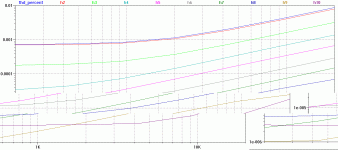
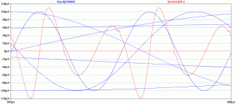
With 1K in series with 56pf there is no oscillation but PM (around 60 degrees) isn't great according to sims.
Optimise in the sims for PM/GM and transfer to real life and I get oscillations. The is no closed loop peaking in the sims. Not massive oscillationbut an extra 50mA is drawn and heat sinks get very hot.
Maybe in real life there is peaking in closed loop response but this isn't shown in the sims. I will be experimenting more tomorrow - I have a plan. 😉
PS. DTMC is superb. It's well worth investigating further. As I said before I got an order of magnitude improvement in THD with no reduction in PM/GM over straight shunt compensation in simulation. it is stable in real life too. The THD improvement was so great that the error correction could be removed.
Edit: edits due to cider consumption.
The shunt comp (I am assuming by this you mean loading the TIS with a cap to ground?) is very sub-optimal from CFA - I have looked into this in the sims and the Alex comp (cap from TIS back to feedback summing node) is much more effective, both in allowing a big reduction in the value of the comp cap and ultimately supporting higher slew rates.
The current-conveyer or current-mirror I see around here are fairly rudimentary and not as accurate as we need or want them to be.
Thx-RNMarsh
Yes, and your models need to be really good if you are to get sensible results. If you start using more advanced current mirrors, the simplicity of the classic CFA is lost, which for me is one of the attractions of this topology.
For practical reasons, a beta enhanced VAS/TIS may be a better option for audio power amplifiers, but I will need to do more work on the two approaches to draw any firm conclusions.
Ref TI? What year? Its about 7 years old and based on infor older than that..... and Mancini did a fair job of making it useful to app engineers but didnt understand it well himself or just oversimplifed too much.
Things changed fast and processes in IC manufacturing changed so that better control and matching can be done more easily.
-RNM
Its lifted straight from their 'Op Amps for Everyone' applications manual - I dont have it up right now, but will try to post the link later.
Re the feedback resistor, I don't think its due to proccess issues (maybe one of the IC gurus can comment?). I would assume writing the ULGF transfer equation would be a simple matter - as is the case for VFA - so why not for CFA?
Surely the TIS [comp] capacitance is known, the level shifter gm is known, the feedback resistor value also . . . so ULGF?
Maybe Prof. Segio Franco can help on this one.
Last edited:
I read it - found it .. my comments stand on the accuracy of info given.
A simple 2 transistor is inadequate, even when matched. At least a three transistor mirror is a much better improvement.
-Richard
A simple 2 transistor is inadequate, even when matched. At least a three transistor mirror is a much better improvement.
-Richard
Re the ULGF, I realised this might actually be a bit more complicated in a CFA.
In a classic MC VFA, you set the - 3dB bandwidth (usually at a low frequency) and the assumption is the response falls off at 20 dB/decade. Its then easy to arrive at the intercept point and theres a standard formular for that. With the classic CFA, since there is no LF dominant pole, you really will end up with a very broad range of ULGF intercepts - and especially so if you are talking wide bandwidth devices where the UGF is up over a GHz (I am talking OPA's here - some devies are at 3-5 GHz).
Practically, since the CFA does not have a fixed gain*frequency response like a VFA, it would follow that at a top level there is not a corresponding ULGF formula as in VFA.
So, while you might be able to put some complicated small signal analysis down on paper for a specific circuit and specific devices, there is no general formula for ULGF. In a CFA you really have to rely more on some rules of thumb and practial testing.
I think this is what Mancini may have been hinting at in CFA opamp devices.
For large signal discrete CFA power amps, we may have a bit more room to play and can see that we develop an approach that starts by deciding what the ULGF is (governed by the output stage phase shift - so my suggested 3 MHz upper limit for modern 30 MHz Ft devices)) then assume 20 dB/decade up until we get to our desired loop gain. This is not too different to what we do with a VFA, and in the CFA we will have to trade loop gain for loop gain -3dB point.
Richard Marsh wrote "A simple 2 transistor is inadequate, even when matched. At least a three transistor mirror is a much better improvement."
Yes, I agree
Yes, I agree
... have yet to see pearls of wisdom. I'm saddened that some important CFA afficianados like LC have been put off and left this thread.
...noise performance... prompted by David Zan's requirements.
If you read any pearls of wisdom send me a PM
Nice to see you look out for my requirements.😉
Another is simplicity...
What level of simplicity do you think acceptable?
At the moment I think a triple OPS and a 2 transistor per side complementary VIS sounds OK.
Add a front end with 6 to 10 transistors (paralleled inputs to keep the noise down adds a few)
LC's VSSA or simple variants give me these characteristics. Diamond inputs lose them.
I don't quite see the point of diamonds but perhaps I miss some essential.
Seems a low impedance LTP is quieter and has better PSRR.
I've done some work on something very similar to VSSA and compared it to a simple VFA that I've worked on for a long time.
I have to say, from now on, I have to look at CFAs very closely indeed.
More to come.
I look forward to it. Have a nice break?
Best wishes
David
The shunt comp (I am assuming by this you mean loading the TIS with a cap to ground?) is very sub-optimal from CFA - I have looked into this in the sims and the Alex comp (cap from TIS back to feedback summing node) is much more effective, both in allowing a big reduction in the value of the comp cap and ultimately supporting higher slew rates.
I find the opposite to be the case. Its well known that you have to take care to minimize capacitances to the inverting input of CFA diamond. Thats exactly the alexander compensation weak point. Richard posted a part of paper warning about this and youll find it in every CFA opamp datasheet, that is because they use diamond buffer front end. Its fine with the alexander amp for it doesnt use a diamond buffer. The use of the alexander compensation causes peaking and I now see you have added some shunt in the latest diagram you posted and probably this is to reduce the peaking. The alexander comp is kind of a shunt. I have seen many commercial op amp diagrams and never seen alexander compensation used by them, and I can guess the reason. Do you have any info where this compensation is used in any CFA opamps from the likes of Texas, Analog devices or Linear technology. Maybe we can get some info regarding this from Scott Wurcer ?
I find shunt comp optimal with CFAs having diamond buffer, that why its used universely by others as well. Ill show some results of what happens when alexander compensaton is I applied to my amp.
That's really strange because I would think the issue is when the capacitance is from the summing junction to GND as you are then putting a zero in the response.
With Alex comp, the cap goes from the TIS to the FB summing junction which is not the same thing. It does introduce a zero, but its well above the ULGF and not a problem.
I've used this on both my sx and nx amps with no problems.
Note I target ULGF at 3 MHz and under in my designs. ( e-Amp VFA was about 1.3 MHz IIRC).
I disagree.
A CFA topology amp is a CFA topology amp. Period.
Changing the feedback resistor value changes the gm. That does not happen on a VFA.
Disagreeing doesn't make your statement right 😛. Take a look at the typical schematic posted here.
The first observation is that in this case the second gain stage is not necessary a TIS, since the input impedance of the emitter follower is much higher than the output impedance of the input stage (R3/2). So the open loop input stage voltage gain is essentially (R3/2)/(R8/2+R21||R33). R33 is the feedback resistor and, as you can easily see, the gain modulation by the feedback resistor happens through the R21||R33 (this is the RF/RG term in my previous post). Because of the large closed loop gain, 18ohm||560ohm doesn't make much of a difference, hence the "CFA" effects are largely diminished, in the 2-5% limits I already mentioned.
Again, this is about the input stage topology (LTP vs. diamond buffer, etc...) rather than any CFA effects which are essentially diminished by the large closed loop gains required for a power amp.
A simulated THD graph at 10Khz and +29.54dB output level ,
that is 30V , on a 8R load , output devices are biased at 78mA/pair.
Numbers are quite good with H2 being in the vicinity of -110dB
below the output level.
ULGF is 8MHz , higher than in the LTSpice sim , surely due
to use of different devices and models.
that is 30V , on a 8R load , output devices are biased at 78mA/pair.
Numbers are quite good with H2 being in the vicinity of -110dB
below the output level.
ULGF is 8MHz , higher than in the LTSpice sim , surely due
to use of different devices and models.
Attachments
The shunt comp (I am assuming by this you mean loading the TIS with a cap to ground?) is very sub-optimal from CFA - I have looked into this in the sims and the Alex comp (cap from TIS back to feedback summing node) is much more effective, both in allowing a big reduction in the value of the comp cap and ultimately supporting higher slew rates.
Yes, I meant loading the TIS. With this form of compensation in my sims I have found that additional shunt compensation was required at the TIS input to get stability.
Even with DTMC (as Manso notes) there still seems to be a requirement for some shunt comp (lead lag) at the TIS output.
Looking at Alexander comp, it looks similar to MIC as detailed in Bob Cordell's book page 181. Is the additional lead lag compensation still required to stabilise the loop in a CFA? Quick sims suggest that it is by looking at the closed loop response.
Waly, please don't become MikeKII.Disagreeing doesn't make your statement right 😛. ..
loadsa sorta good stuff
...Again, this is about the input stage topology (LTP vs. diamond buffer, etc...) rather than any CFA effects which are essentially diminished by the large closed loop gains required for a power amp.
You are obviously at least as well read as him but have far greater theoretical (& more importantly, practical) understanding of the issues. As such, you have much useful stuff to teach us unwashed masses ... instead of the names of obscure authors and arguments over further obfuscating TLAs ...
May I suggest you prepare some labels which say 'input stage topology (LTP vs. diamond buffer, etc...)' and stick them to your screen over 'CFA Topology' when you look at this thread? 😉
Quite sincerely .. if a little tongue in cheek .. 🙂
ULGF is 8MHz , higher than in the LTSpice sim , surely due to use of different devices and models.
I plead ignorance, somebody please come up with an example of commercial audio power amp having 8MHz ULGF.
7-8MHz ULGF (and in particular for a bipolar output stage) is way to high to be of any practical importance.
For a VFA at 50W 8R 100W 4R, the attached circuit sims at <1ppm THD up to 20kHz and is good for overload/stability/loads bla bla etc. It has 16 active devices. It's simplicity is deceptive. I've agonised over every single component over some 30+ yrs. I'm still learning new stuff about it .. most recently, from Dave Zan, about the true effect of C9 which I've yet to investigate fully.What level of simplicity do you think acceptable?
At the moment I think a triple OPS and a 2 transistor per side complementary VIS sounds OK.
Add a front end with 6 to 10 transistors (paralleled inputs to keep the noise down adds a few)
(Most) more complex amps of similar size are far from that level. It's close enough to stuff I've burnt solder over to be confident, given the right PCB layout, decoupling & earthing .. it will have single digit PPM THD in the audio range.
IMveryHO, I don't think a more complex 50W 8R VFA is worthwhile. For 200W 8R, things are much more complicated and something like astx's 2stageef-high-performance-class-ab-power-amp-200w8r-400w4r may be required. But I've not designed or built anything of that size.
Attachments
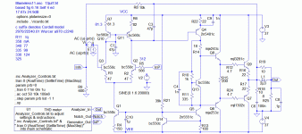
This is my CFA offering. It started of as something for Dave Zan .. then I realised that JLH had several designs of almost identical topology. LC's VSSA is also very similar.
I've not fully looked at this in SPICE world and more importantly, have never burnt solder on anything similar.
- I haven't used VSSA cos proper THD analysis needs EKV MOSFET models (hint hint grovel grovel Guru Cordell) The DC design is VSSA with FET CCSs on the i/p. I'm not sure how to sensibly tweak them in production .. or even for a one off.
- V4 & 5 are just to charge C3 & 4 for the THD analyser to work easily.
- C1 & 2 would be large in 'real life'
- The design has very low i/p noise, basically just R12=14R if the transistors are good. But for Dave Zan's supa LN application, it should only 2.555x gain rather than 17.67x as here. R12=39R R18=110 for Dave Zan's treble amp
- It uses 11 devices.
I've not fully looked at this in SPICE world and more importantly, have never burnt solder on anything similar.
Attachments
Last edited:
I plead ignorance, somebody please come up with an example of commercial audio power amp having 8MHz ULGF.
7-8MHz ULGF (and in particular for a bipolar output stage) is way to high to be of any practical importance.
Agree that it seems to have no practical importance for audio amps
given that it s not like we start with considerable loop gain at the
frequencies of interest.
The good THD ratio is firstly due to the linearity of the circuit
at OLG not to its eventual speed wich is wrongly assumed by some
as being parameter that can add or be traded for more linearity.
As for commercial amps Accuphase is a proponent of these
kind of amplifiers but i have no clues about their specs
let alone a parameter as ULGF that is never speced
even for the ubiquitous VFAs.
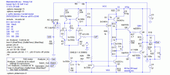
I attach the simplest VFA design which might meet the approval of this august company. It has several well known (??) THD mechanisms which are addressed in Blameless6 but I've a lot of experience, both 'real life' & sim, with it.
It uses 13 devices.
_________________
Please excuse me for posting evil VFA circuits on this thread but I feel the discussion shouldn't be about fudges to either VFAs or CFAs. Instead, they should be the best possible for a given level of complexity.
I can't claim my CFA example is the best possible but I will claim at least long familiarity with the 2 VFA designs here.
_________________
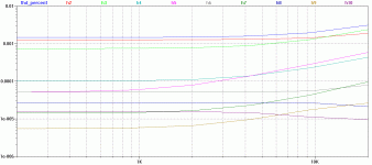
The simple VFA has about 1/2 the LF THD of the CFA but 3x more at 20kHz. It uses an extra 2 devices.
As the CFA is symmetrical, we can only add '1' extra device in the forward path if we use these extra 2 devices.
I'm hoping this thread will tell me how to best use these 2 bits but I would be disappointed if adding an extra device didn't reduce THD by at least 10dB at all frequencies.
This would give the simple CFA the lead over the simple VFA in all respects.
_________________
Lastly, though I've offered my caveats about not having burnt solder over the CFA, the real caveat is that in my previous life, I was a true Double Blind Listening Test guru (I was only a pseudo electronics/mike/speaker guru 🙂 )
I have never carried out DBLT bla bla on CFA vs VFA. But at a given level of THD performance, the limited tests I've done on (VFA) amps suggests that simpler designs sound better.
It is likely the simpler amps had better behaved overload and stability characteristics.
I share Bob Cordell's suspicion that these may be the most audible characteristics of amps rather than ppm THD.
Attachments
Yes, I meant loading the TIS. With this form of compensation in my sims I have found that additional shunt compensation was required at the TIS input to get stability.
Even with DTMC (as Manso notes) there still seems to be a requirement for some shunt comp (lead lag) at the TIS output.
Looking at Alexander comp, it looks similar to MIC as detailed in Bob Cordell's book page 181. Is the additional lead lag compensation still required to stabilise the loop in a CFA? Quick sims suggest that it is by looking at the closed loop response.
No, I am not finding that additional shunt comp is needed in sims, or in practice (sx and nx amps). The 1 pF you see for the shunt cap in the circuit I posted is a place holder. I did some sims yesterday on this very issue, and will stick with Alex comp in my designs for now, in addition of course to exploring other comp options.
- Home
- Amplifiers
- Solid State
- CFA Topology Audio Amplifiers

