Let us not confuse details and personal opinion with what works. There is NO perfect fit, just a 'best fit' and that may be the difference between extra low measured thd distortion and lower high order distortion.
Last edited:
What if ---- the bias was allowed to creep upward slightly with temp. This would happen during playing music. Is this bad from a listening/measurement point of view as long as thermal runaway does not occure?
The Marantz MM7025: Uses a pair of 2SC2922/2SA1216 OPS. They set the idle at 15 mA and the Re is 0.1 Ohm. It has an internal fan for the heat sink tunnel. The idle creeps upwards in use.
Thx-RNMarsh
The Marantz MM7025: Uses a pair of 2SC2922/2SA1216 OPS. They set the idle at 15 mA and the Re is 0.1 Ohm. It has an internal fan for the heat sink tunnel. The idle creeps upwards in use.
Thx-RNMarsh
Last edited:
What if ---- the bias was allowed to creep upward slightly with temp. This would happen during playing music. Is this bad from a listening/measurement point of view as long as thermal runaway does not occure?
The Marantz MM7025: Uses a pair of 2SC2922/2SA1216 OPS. They set the idle at 15 mA and the Re is 0.1 Ohm. It has an internal fan for the heat sink tunnel. The idle creeps upwards in use.
Under biasing is very common in commercial power amplifiers, in particular for those "mid-fi". It is intended to lower the idle power dissipation (and hence save in the heat sink size). These manufacturers already know that the common customers will never find out, based on hearing only, that the amplifier has (because of the under biasing) a poor distortion spectra distribution.
It is also common that such amplifiers would succumb at the 1/3 nominal power test (the maximum power dissipation regime). Of course, having a forced convection fan helps, this Marantz may survive.
I suspect the bias is not set low because of power dissipation, but because of bias creep as temp rises. Most heatsinks will easily cope with 50 mA per pair idle dissipation vs say 20 mA (that's low power in the context of things) so what's the point then of setting it at some much lower figure as we typically see? The reason is as the amp warms up, the bias increases such that at normal operating levels after 30 mins or so, the bias is about right. This is what I call single slope temperature compensation. Where it actually settles, and what assumptions are used are a matter of choice on the designers part.
The idea is to get the ideal current and temperature to intercept at 2 points, rather than 1 point, by design rather than luck. I wrote up my thoughts on this a few years ago after working on my original 250 Watt EFT amplifier from 2007/7. On a later design, the e-Amp, I used an NTD to basically do the same thing.
Most bias schemes are single slope and when you read Self's or Bob Cordell's on this specific subject, you can see it is an exercise in compromise rather than a solved problem.
For EFT, I am an advocate two slope or two point thermal comp, which seems to improve things markedly i.e. the bias current is much more stable over a wider junction temp - the Thermaltrak devices are also an attempt and a useful tool to solve this problem. The issue is much less of a problem on EF2's - EF3's are an entirely different matter though.
http://hifisonix.com/audio-amplifier-temperature-compensation/
Last edited:
I suspect the bias is not set low because of power dissipation, but because of bias creep as temp rises. Most heatsinks will easily cope with 50 mA per pair idle dissipation vs say 20 mA (that's low power in the context of things) so what's the point then of setting it at some much lower figure as we typically see?
20mA vs. 50mA is 2.5 times the idle power, not to mention that 50mA would be ideal for 0.5ohm emitter resistor, which is already very large.
Consider 6 pairs at +/-70V, that's 25W of extra idle power per channel. Such an amplifier would deliver some 250W into 8 ohm.
The worst case dissipation is about 350W (at about 1/3 the maximum output power). Indeed, 25W of extra power are in this case not a big deal however, at a reasonable average level of 50W (20Vrms in 8 ohm, which is already very loud music), the power dissipation is about 110W plus any idle power dissipation which, in this case, is over 20%.
Very, very few commercial amplifiers are designed to thermally survive the worst case power dissipation, on the long run, at least not without forced cooling. Interesting enough, DIY power amplifiers are usually much more conservative in designing the thermal budgets than most of the commercial amplifiers.
Waly, 20mA to 50 mA is not a big deal. If you have thermal run away at those levels you assuredly have problems other than the additional 30 mA Idle current.
More to the point, on a 0.22 RE design, ignoring intrinsic emitter resistance and reflected base resistance for the minute, the ideal Iq is 0.026/RE = circa 78mA. But, we regularly see Iq set to half the correct figure or lower. My bet is its because after the amp had warmed up the Iq settles at the correct figure - the result of single point thermal comp.
I agree that run of the mill commercial amps are by and large not designed to handle worst case dissipation - there's loads of those in the Stereophile review library that failed the 1/3 power test.
Last edited:
More to the point, on a 0.22 RE design, ignoring intrinsic emitter resistance and reflected base resistance for the minute, the ideal Iq is 0.026/RE = circa 78mA.
Ummm... I'm half asleep but even so I can tell 0.026V/0.22ohm=118mA
You're right - that's what happens when you get old. And I also just realized that in post #4459 I should have written 0.33 Ohms and not 0.22 Ohms. I run the nx-Amp at 125mA per pair with 0.33 Ohms RE
What if ---- the bias was allowed to creep upward slightly with temp. This would happen during playing music. Is this bad from a listening/measurement point of view as long as thermal runaway does not occure?
Thx-RNMarsh
PS -- As I ran the bias up, with thd at 10W/8Ohm, the reduction in the distortion stopped if I ran the bias up past 40-45mA at which point the THD didn't go lower with more bias. But with music, it moves up but never caused the heatsinks to become too hot (or a thermal switch would shut down the amp).
Seems like it might be a good thing to have the bias move up with music playing...greater Class A
THx-RNMarsh
Last edited:
Hey , CFA people. NAF in indonesia has the very first CFA I designed in this
thread up and running. (NX with hawksford/servo) 🙂
Worked the first time.
The servo keeps offset at 1.2mv ... period, no change. And the EF3 bias stays
within 1mV , no change. Bimo's EF3 also .. rock solid.(he chose a VFA 🙁 )
NAF says not even a hint of ringing/oscillation , any test.
Thank you bonsai and others for an excellent learning experiance. Now I'm
a "VFA/CFA man". 😀
😎😎
OS
Originally Posted by RNMarsh
Seems like it might be a good thing to have the bias move up with music playing...greater Class A
As in Dynamic Class A ? Sure, not a new concept though 😉
Hey , CFA people. NAF in indonesia has the very first CFA I designed in this
thread up and running. (NX with hawksford/servo) 🙂
Worked the first time.
The servo keeps offset at 1.2mv ... period, no change. And the EF3 bias stays
within 1mV , no change. Bimo's EF3 also .. rock solid.(he chose a VFA 🙁 )
NAF says not even a hint of ringing/oscillation , any test.
Thank you bonsai and others for an excellent learning experiance. Now I'm
a "VFA/CFA man". 😀
😎😎
OS
Great result OS and NAF! Hope to see more designs like this up on the forum!
😎
PS -- As I ran the bias up, with thd at 10W/8Ohm, the reduction in the distortion stopped if I ran the bias up past 40-45mA at which point the THD didn't go lower with more bias. But with music, it moves up but never caused the heatsinks to become too hot (or a thermal switch would shut down the amp).
Seems like it might be a good thing to have the bias move up with music playing...greater Class A
THx-RNMarsh
This is very easy to arrange in class A. I used 2N7002, 2 or 3 resistors, 2 diodes and a small cap. When the music plays, it runs in class A. When the music stops or is low level, it runs in class AAB. I am definitely going to do this on my next class A amp.
Kudos to DA who thought of the idea years ago at Krell. JC also has something similar but with op-amps etc.
However, I'd like to think my implementation is the most elegant 😀
Attachments
Last edited:
Hey , CFA people. NAF in indonesia has the very first CFA I designed in this
thread up and running. (NX with hawksford/servo) 🙂
Worked the first time.
The servo keeps offset at 1.2mv ... period, no change. And the EF3 bias stays
within 1mV , no change. Bimo's EF3 also .. rock solid.(he chose a VFA 🙁 )
NAF says not even a hint of ringing/oscillation , any test.
Thank you bonsai and others for an excellent learning experiance. Now I'm
a "VFA/CFA man". 😀
😎😎
OS
Congrates! Thats great news. We need more confidence in going from SIM's to working unit and this helps. Now, does the distortion measurements under load match the SIM?
Thx-RNMarsh
This is very easy to arrange in class A. I used 2N7002, 2 or 3 resistors, 2 diodes and a small cap. When the music plays, it runs in class A. When the music stops or is low level, it runs in class AAB. I am definitely going to do this on my next class A amp.
Kudos to DA who thought of the idea years ago at Krell. JC also has something similar but with op-amps etc.
However, I'd like to think my implementation is the most elegant 😀
It may be just as easy to do with 'standard' bjt bias spreader circuit and zener to limit bias to a plateau. Can you SIM this for us for EF, 2EF and 3EF? A cap to slowly lower bias?
My point was many circuits have 'fixed' bias while sliding upward in a controlled manner is a good thing.
Thx-RNMarsh
Last edited:
Hey , CFA people. NAF in indonesia has the very first CFA I designed in this
thread up and running. (NX with hawksford/servo) 🙂
Worked the first time.
The servo keeps offset at 1.2mv ... period, no change. And the EF3 bias stays
within 1mV , no change. Bimo's EF3 also .. rock solid.(he chose a VFA 🙁 )
NAF says not even a hint of ringing/oscillation , any test.
Thank you bonsai and others for an excellent learning experiance. Now I'm
a "VFA/CFA man". 😀
😎😎
OS
OS, First I tried my CFA and burned 2 feedback resistor 😱. And then I choose to finish my VFA. But right now, I can made my CFA singing 😎. I listening one VFA and one CFA in stereo 😀.
I develop test procedure to each module before they connected.
For OPS, I use your suggestion to put 2 resistor to simulate VAS current.
FOR IPS, I just connect VAS+ output, VAS- output, and Feedback.
I found designing CFA is more challenging than VFA.
I will try many IPS topology.
Let us not confuse details and personal opinion with what works. There is NO perfect fit, just a 'best fit' and that may be the difference between extra low measured thd distortion and lower high order distortion.
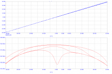
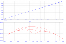
Output stage (MJL1302/3281) + driver only, 4 pairs of output devices, transfer function vs. idle current. Re = 0.22
Attachments
Last edited:
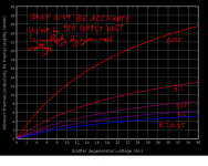
I made an interesting graph. It shows the minimum W/mK (per supply volt) junction-heatsink conductance at which BJTs will experience differential thermal runaway, or current hogging.
So say you have a dual paralleled EF with 0.15R emitter resistors biased at 12mV, and a supply of 60V. We see about 4.7W/mK (per volt) where the .15R line and 12mV intersect. So 60V * 4.7W/mK = 282W/mK. Converting conductivity to resistance, this comes to 3.55R thermal resistance between a transistor and the heatsink. You probably want at most 1/5 of this.
This may seem a bit awkward but it was the best way I could find to represent the data with the least assumptions. The assumptions I DID make are:
1: Vbe tempco = 2.2mV/C
2: Hfe tempco negligible.
3: Degen voltage up no larger than 36mV.
Bob's MJL models seem to have 1.7mV/C tempco, so #1 may be conservative. The severity of #2 is worse with lower degeneration voltage.
Paralleled outputs are so susceptible to differential thermal runaway because the Vbe multiplier is blind to differential thermal errors. So the Vbe multiplier cannot compensate for differential thermal stability. If you had thermal compensation applied to each output transistor, this wouldn't be a problem. As JC said, if you only have one output pair, you can get away with much lower emitter resistors. If you have thermal compensation for each individual transistor, and the factory Vbe spread wasn't too high, you could probably do the same with paralleled outputs.
This also brings up a problem with the idea of having a discrete driver for each output. The drivers themselves in this case will add to the differential thermal runaway.
It is also useful to have this information for TO92 and TO220 size transistors where they would be highly paralleled, as in a low-noise circuit, or paralleled output drivers.
My interest with lowering emitter resistors is to allow the 13mV bias point without sacrificing Ft with low bias. The 13mV bias point could have the same first-watt THD as a GM-doubled bias point, but they would have odd order harmonics of the opposite polarity. For this reason I suspect the low bias point may sound better and be more economical.
Attachments
Sorry I mean models are quite bad.
Both good and bad are available.
In the same place...
Start! Fetch!
Look at the menu selection named "LT Spice Models"
Right click, save as. . .
The deal is that the GOOD models have annotations or "suffixes" to indicate that they have been proofed and by whom.
Those without suffixes are better than a power outage only because they exist and *may be* better than nothing.
- Home
- Amplifiers
- Solid State
- CFA Topology Audio Amplifiers