I've built 2 CFA power amps (sx and then nx) using the diamond buffer and they are exceedingly good DC wise. nx-Amp for example starts out at about 15mV of offset at switch on, and within 2-3 minutes its at 1-2mV where it stays put. sx is class A, and it starts out at about 50mV and once warmed up (10-15mins) it also settles at 1-2mV. The sx is under 10mV within about 2 minutes of switch on anyway. Bottom line: For power amp applications, CFA DC performance is superb.
However, I just remembered you are using CCS bias for the buffers, so you may not be able to use a simple offset adjust pot and resistor into the summing junction. I use Zeners to regulate the front end supply and I connect a pot across them and a resistor from the wiper to the summiung junction.
If you stick with the CCS's, I'd do what you have to to ditch the cap - looks like a servo is the way you have to go.
TL071 JFET input OPAMP should do the trick - good for about 5mV offset absolutely worst case, generally more like 2-3mV. Hi-z input is useful for the servo integrator where the resistor is usually 100's of k to 1MEG.
Cheap an plentiful from Mouser, DK etc.
Cheap an plentiful from Mouser, DK etc.
OS.... does the servo increase noise? Otherwise seems fine to me.
Thx-RNMarsh
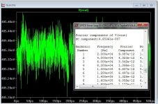
I'll show you (below) ... this is LT's model , keep in mind.
(calculate that DC component)
As far as noise , I'm "lifted" through a 220K resistor...the LT1001 is additionally decoupled with 2 diodes/10u caps (titan amp). Any noise
would be the op-amps's ... but then attenuated by the 220K.
The good thing , is that 20hz THD is .0032%- 2R !
PS - I already have the board "decapped" with the 12V+/- at the NFB node.
easy to integrate - no major rework of the IPS PCB. 😎
OS
Attachments
TL071 JFET input OPAMP should do the trick - good for about 5mV offset absolutely worst case, generally more like 2-3mV. Hi-z input is useful for the servo integrator where the resistor is usually 100's of k to 1MEG.
Cheap an plentiful from Mouser, DK etc.
TL071 it is !
2mA low current. LT's 1001 reads 2.7mA .. I'm trying to keep
to my 14-16ma / per rail IPS "target". Jfet input .. I could most
likely raise my input resistance considerably .
(mouser has 2K in stock at $.62 each !)
Now to get a model - I'm sure it will be similar to the 1001.
PS - just measured my Sansui Z3900 servo EF3 (ne5532) ... .2mV - it been there for 33 years !
OS
Last edited:
Richard, a TAS (i.e. current mirror) second stage would probably be the only real difference in the 2nd stage between a CFA and a VFA. I think the point Bob was making is that the main difference is in the front end stage, since CFA can be used with conventional VAS stages as used in VFA's as well.
For IC's, it seems that a TAS is best because you get the very wide bandwidths of the mirror structure, plus a wide bandwidth OPS (which you cannot do easily in a power amp) so this overall approach really plays to the wide band strengths of the CFA.
OK. Could be used with conventional VAS (but CFA don't). Don't know how that observation helps one design CFA... unless just to narrow the 'main' differences down.
But yes; it also seems pretty obvious that CFA IPS is not used with VFA. It is a subtle change but isn't a trivial topology change, however.
One point that is mentioned in the literature --- CFA only use complimentary symmetrical topology. This gives lower distortion (at any gain). Some VFA now use similar compl/symmetry in the 2nd stage and close the distortion performance gap. But there still remains performance differences which make CFA the go-to topology of OEM's world-wide for decades.
But, the question remains... will we/DIY'er ever get a book about it for audio? A chapter would be a great beginning to expand on and then into another book... could be a strategy. Otherwise, years from now this forum/thread will be hard to find and read without editing. Plenty of user help is available with circuit examples and input and even contributors.
Thx-RNMarsh
Last edited:
Some VFA now use similar compl/symmetry in the 2nd stage and close the distortion performance gap. But there still remains performance differences which make CFA the go-to topology of OEM's world-wide for decades.
But, the question remains... will we/DIY'er ever get a book about it for audio? A chapter would be a great beginning to expand on and then into another book... could be a strategy. Otherwise, years from now this forum/thread will be hard to find and read without editing. Plenty of user help is available with circuit examples and input and even contributors.
Thx-RNMarsh
Maybe it is long time ago that designer use symmetrical design (LTP and VAS) for VFA. I used them for my self (DIY) 12-11 year ago. Now, I compare it against CFA.
I agree to make another thread for discuss how to make trade-off decisions (strategy?) in design.
Last edited:
1: Right. I would write "smaller", as the base parasitic capacitance is higher than the emitter one.1- I assert that I can make the LTP of a VFA have just about as little added HF phase shift as the input stage of a CFA, especially if I am allowed to make the impedances in the feedback network just as small.
2- Finally, I'll assert that the speed of the output stage strongly dominates the limit of how high ULGF can go in a power amplifier.
2: Really ? Even with power FETS ? On my experience, with practical devices, all the stages have , more or less, around the same FC.
http://www.esperado.fr/temp/VSSA/vssa-vs-vfa.htmlThe OPS, yes. But same VAS? Really? wow!
1: Right. I would write "smaller", as the base parasitic capacitance is higher than the emitter one.
2: Really ? Even with power FETS ? On my experience, with practical devices, all the stages have , more or less, around the same FC.
http://www.esperado.fr/temp/VSSA/vssa-vs-vfa.html
Esperado, I read your website. It is great work. Nice. IMD is the same for both topology, but THD the CFA is slightly lower than VFA. The cause of IMD must be different than the cause of THD. According Bob Cordell in the previous thread, the cause of IMD and THD is same. Maybe I must try to reduce THD in the same amp to see if IMD is reduce too.
1: Right. I would write "smaller", as the base parasitic capacitance is higher than the emitter one.
2: Really ? Even with power FETS ? On my experience, with practical devices, all the stages have , more or less, around the same FC.
http://www.esperado.fr/temp/VSSA/vssa-vs-vfa.html
Good work

Thanks for your kind words.IMD is the same for both topology, but THD the CFA is slightly lower than VFA. The cause of IMD must be different than the cause of THD. According Bob Cordell in the previous thread, the cause of IMD and THD is same. Maybe I must try to reduce THD in the same amp to see if IMD is reduce too.
I was very involved to understand the differences between the two topologies.
Made several CFA-VFA versions in real word of the same amps to figure out where and what differences.
Yet unable for the moment to get definitive conclusions. The only thing i take for granted is i always preferred the CFAs versions, and the differences between them on measurements were always better slewrate for CFAs and better PSRR for VFAs.
It was always very fast amps, with fets OPS.
Nothing really determinant between them, HD or IMD side, apart better at HF for CFAs, with more phase margins and more consistent square waves between little signals and large ones. .
I've done some more work on my sims. I need to extend the analysis next to higher CLG conditions to confirm my conclusions.
Re the lower THD observed in some CFA vs VFA comparisons (I don't think this can be taken as a blanket statement by the way) it can be explained by the higher loop gains at HF. My investigation shows that for the same PM at each of the two topologies ULGF, the LG in CFA can be up to 12 dB higher.
At LF, VFA wins. Period.
Last edited:
I've done some more work on my sims. I need to extend the analysis next to higher CLG conditions to confirm my conclusions.
Re the lower THD observed in some CFA vs VFA comparisons (I don't think this can be taken as a blanket statement by the way) it can be explained by the higher loop gains at HF. My investigation shows that for the same PM at each of the two topologies ULGF, the LG in CFA can be up to 12 dB higher.
At LF, VFA wins. Period.
I hope you will share the result.
Now, can we made VFA as woofer amp and CFA as tweeter amp 😉 ?
Definitively, YES !Now, can we made VFA as woofer amp and CFA as tweeter amp 😉 ?
(Using VFAs in their flat open loop range with a HF margin)
Agree. The problem is, when you compare the two input topologies, everithing equal else were, one of them will not be optimal.I don't think this can be taken as a blanket statement by the way
To resume with other words, i tend to prefer CFA to VFA (on large band amps), based on long and various listening experiences. I am unable to justify my preference with numbers or pure technical argumentation.
Not a good basis to argue against Wally (or D Self'), who never listened to CFAs, as far as i understand.
With age, i tend to lie on my instinct and my listening experience more and more, and to use my (little) technical knowledge as just a component of it. And, after all, i'm not involved any more with industry: just with my personal listening pleasure ;-)
Too much things about reproduction differences i cannot explain in a definitive way by pure science or maths.
I feel more comfortable with Mr Cordell's way to deal with all the technical aspects: Try, build, listen, with a virgin attitude, get some kind of simple feelings about each assembly (the way they sound if any) and try to understand why, when it is possible.
btw: When it is possible, it leads usually to a very simple explanation.
Last edited:
cascode
Not surprisingly, the 2SC3503 does a better job, Zo = 151 Meg. Compared to a BC850, I 'only' got 42 Meg. Why is the 2SC3503 way better? Just as you said already, not just because the Early voltage is huge, rather its figure of merit (FOM=VA*beta) is exceptional high. Comparing this one to an ordinary mainstream tranny is bit of an apples to oranges comparison.
I also agree with Bob, who remarked: "... it is nice to use a transistor with a higher FOM - just as it is nice to do with a non-cascoded VAS transistor."
Bottom line: when selecting the proper tranny for a cascode, we should look at both the Early voltage and beta.
BTW, not that it really matters, but I think that Glen's VAF=1000 is a little too high. I've also seen the picture from Glen's curve tracer and, as far as I remember, VAF is somewhat lower at higher currents (Ic>10mA).
BTW2, the original Sanyo 2SC3503 was quite expensive. I wonder if the cheaper Fairchild KSC3503 is just as good. Any idea?
Here is what I said:
- "Regarding the common base stage of the cascode, I could be missing something, but IMO a high Early voltage device is mandatory." I was wrong, because I was assuming also: "Cascoding two identical devices doesn't make much sense." which is also wrong, as shown by Marcel. The confusion was coming from my mosfet world, where because of the very low transconductances (compared to bipolars) nobody sane is going to cascode two identical devices and take advantage of the Ro multiplication. You cascode a relatively short channel mosfet (high transconductance, but low Ro) with a relatively long channel mosfet (low transconductance but high Ro).
- However, if you cascode a high beta device (BC550) with a high Early voltage (as the 2SC3503) that should be better than cascoding two BC850. Indeed, the 2SC3503 process has a much higher figure of merit (Beta*VA) compared to the BC550.
[..]
Not surprisingly, the 2SC3503 does a better job, Zo = 151 Meg. Compared to a BC850, I 'only' got 42 Meg. Why is the 2SC3503 way better? Just as you said already, not just because the Early voltage is huge, rather its figure of merit (FOM=VA*beta) is exceptional high. Comparing this one to an ordinary mainstream tranny is bit of an apples to oranges comparison.
I also agree with Bob, who remarked: "... it is nice to use a transistor with a higher FOM - just as it is nice to do with a non-cascoded VAS transistor."
Bottom line: when selecting the proper tranny for a cascode, we should look at both the Early voltage and beta.
BTW, not that it really matters, but I think that Glen's VAF=1000 is a little too high. I've also seen the picture from Glen's curve tracer and, as far as I remember, VAF is somewhat lower at higher currents (Ic>10mA).
BTW2, the original Sanyo 2SC3503 was quite expensive. I wonder if the cheaper Fairchild KSC3503 is just as good. Any idea?
One last thing i would like to present to your thoughts.
I tend to think that the absolute amount of feedback is not the main criteria.
I don't fully agree with Bruno's statement: "When you use feedback, use a lot", as increasing the feedback ratio, after an optimal point, sometimes deteriorate the listening result.
Absolute feedback ratio is, on my opinion, less important than the linearity of the feedback in the bandwidth we want to reproduce.
Our power amplifiers with the fastest devices we can find are not yet fast enough to gives us a 20KHz flat open loop. (Means a flat feedback ratio in all the audio bandwidth)
If an amplifier was able to this, i would not ask myself questions about CFA or VFA, and use-it.
BY habit, a CFA amp have something around one octave more flat open loop bandwidth than its CFA brother.
May-be there is the main difference ?
That, and the expansive behavior, as the main sound-stage difference is on little transients (details).
Last edited:
At LF, VFA wins. Period.
Not quite, remember this http://www.diyaudio.com/forums/solid-state/240712-cfa-topology-audio-amplifiers-213.html#post3714654
The power of the Edmond's CMLC...?
I'm talking about practical amplifiers, not something in a sim. The LF loop gain in a VFA can be made very high, and the result is lower distortion.
Last edited:
I'm talking about practical amplifiers, not something in a sim. The LF loop gain in a VrFA can be made very high, and the result is lower distortion.
Way do you think it could not be made practical amplifier from that one?
- Home
- Amplifiers
- Solid State
- CFA Topology Audio Amplifiers