Recall, I said I didn't need to use compensation caps anywhere in a CFA? Here's the deal: If you use low Z values in the circuit, the stray C's from anywhere (pcb, wiring, transistors) will not have much affect on distortion nor limit BW. You will have a very wide BW circuit. AND, if you have followed the study lessons here, in a very good CFA the BW is controlled by Rf resistor value. For example, for a given BW using a given Rf, if you double the Rf, the BW is halved. So. By carefully choosing the Rf value, and throwing away some unneeded BW, you can have a very stable circuit.
[I hope this makes some sense 'cause I really don't want to explain it]
Thx-RNMarsh
[I hope this makes some sense 'cause I really don't want to explain it]
Thx-RNMarsh
Last edited:
Not that much. Perhaps the moderation team is able to do a better job. 🙄Have you started the year with the firm resolution to believe in Santa Claus?
You're welcome.Btw: Thanks for so many clever and useful analyses you bought to the community, Ed.
Cheers, E.
So increasing VA is of no use, as at the same time beta will decrease. As a result, the output impedance doesn't rise at all. Even worse, a higher Early voltage is counterproductive! I've simmed a cascode with several trannies and in every case the output impedance decreased somewhat after doubling VAF and halving BF
That's not what I said. Because you are at it, compare a BC850 cascoded with an identical BC850 then a BC850 cascoded with a 2SC3503. Which one is better? You'll then find out what I said.
You're welcome.
The enemy of my enemy is my friend, isn't it? 🙄.
I don't know what you are talking about, but this is what you have said:That's not what I said.
"Regarding the common base stage of the cascode, I could be missing something, but IMO a high Early voltage device is mandatory." (post 3638)
If you give me the correct models or parameters, then I'll give you the answer.Because you are at it, compare a BC850 cascoded with an identical BC850 then a BC850 cascoded with a 2SC3503. Which one is better? You'll then find out what I said.
edit: As you can see, I've removed you from my ignore list; hope I don't regret it.
Last edited:
I don't know what you are talking about, but this is what you have said:
"Regarding the common base stage of the cascode, I could be missing something, but IMO a high Early voltage device is mandatory." (post 3638)
If you give me the correct models or parameters, then I'll give you the answer.
edit: As you can see, I've removed you from my ignore list; hope I don't regret it.
Here is what I said:
- "Regarding the common base stage of the cascode, I could be missing something, but IMO a high Early voltage device is mandatory." I was wrong, because I was assuming also: "Cascoding two identical devices doesn't make much sense." which is also wrong, as shown by Marcel. The confusion was coming from my mosfet world, where because of the very low transconductances (compared to bipolars) nobody sane is going to cascode two identical devices and take advantage of the Ro multiplication. You cascode a relatively short channel mosfet (high transconductance, but low Ro) with a relatively long channel mosfet (low transconductance but high Ro).
- However, if you cascode a high beta device (BC550) with a high Early voltage (as the 2SC3503) that should be better than cascoding two BC850. Indeed, the 2SC3503 process has a much higher figure of merit (Beta*VA) compared to the BC550.
.model BC850CN NPN(Is=7.049f Xti=3 Eg=1.11 Vaf=29.03 Bf=462.4 Ise=57.19f
+ Ne=2.002 Ikf=.1609 Nk=.6124 Xtb=1.5 Br=3.988 Isc=10.68f
+ Nc=2.417 Ikr=2.721 Rc=1.374 Rb=100 Cjc=7.287p Mjc=.3333 Vjc=.5 Fc=.5
+ Cje=9.485p Mje=.3333 Vje=.5 Tr=10n Tf=663.1p Itf=1.423
+ Xtf=14.94 Vtf=10)
.MODEL Q2SC3503 NPN(
+ IS=7.010E-13
+ BF=156.09
+ IKF=0.12325
+ ISE=1.2538E-14
+ NE=1.5
+ BR=0.64499
+ VAR=100
+ IKR=0.05102
+ ISC=6.4644E-09
+ NC=1.5
+ RE=0.108
+ RC=1.215
+ RB=12.134
+ RBM=0.034
+ IRB=3.0e-6
+ VTF=35
+ TR=1.0E-8
+ EG=0.76
+ XTB=1.5
**-------------------------------------------------------------------
** Parameters modified by Andy
**
** Early Voltage from Glen's curve tracer measurements
+ VAF=1000
**
** fT-related parameters from Matlab optimization
+ CJC=11.35E-12
+ MJC=0.3160
+ VJC=0.2
+ FC=0.950383
+ TF=1.6933e-010
+ XTF=10000
+ CJE=5.621e-011
+ VJE=0.645139
+ MJE=0.6
+ ITF=7.50579)
There is absolutely no technical reason that would make this statement true, and repeating it also doesn't help.
Shunt lag compensation is probably the worst compensation method.
The only case in which a lead-lag shunt compensation can be really useful is to compensate the Miller loop.
Hello ,
Why do you consider that shunt is worst ?Why all the engineers are looking only at the gain in the loop ,that beeing a good criteria ?
The shunt compensations intoduces the smallest group delay and also the highest bandwidth .Make a simulation
Burr-Brown Notes on Stability for CFA
Burr-Brown (TI) App Bulletin: "Current Feedback Amplifiers: Review, Stability Analysis, And Applications."
View attachment B-B CFA.pdf
View attachment B-B CFA-2.pdf
View attachment B-B CFA-3.pdf
Thx-RNMarsh
Burr-Brown (TI) App Bulletin: "Current Feedback Amplifiers: Review, Stability Analysis, And Applications."
View attachment B-B CFA.pdf
View attachment B-B CFA-2.pdf
View attachment B-B CFA-3.pdf
Thx-RNMarsh
Bob, I don't think the ULGF should be above the OPS pole so we are in agreement.
I am simply saying that the lower OLG on CFA's means less of the phase shift at HF is exposed before the typical ULGF of VFA's. (Note I am not saying that high gain= phase shift)
I think this explains why CFA is more tolerant of cap loads, and they are easier to comp.
Again, I am not dissing VFA - I've built and listen to both types. 😎
Hi Bonsai,
Thanks for your answer. I don't think you have been dissing VFA, and I have not been dissing CFA. I think we both agree that asking the tough questions about either is not dissing, but rather an honest search for understanding.
When we talk about lower OLG of a CFA, we need to do it in the context of frequency. For example, extremely high OLG at low frequencies need not have any effect on what is going on at the ULGF. We need to talk about where in frequency the OLG is lower.
I always assume that with conventional compensation the loop gain has been rolling off prior to ULGF for more than a decade, so that the dominat pole is contributing nearly its full 90 degrees. Are you saying that in the CFA the OLG is lower to the point where the dominant roll-off has not yet contributed nearly its full 90 degrees by the time we reach ULGF(thus allowing more room for other sources of phase lag)?
In any amplifier, be it CFA or VFA, the loop gain must decline from a large value to unity in some way by the time we reach ULGF; and that decline necessarily adds phase lag.
Note also that even in a Miller-compensated VFA, we are always free to rid ourselves of some of that 90 degrees from the main roll-off by adding a zero to the Miller roll-off with a resistor in series with the Miller capacitor - I have sometimes done that. It can be used to cancel another pole, for example. So I believe it is just as easy to play the same game with a VFA in a very straightforward way (if that is the game you are describing - maybe I have it wrong).
Let me put it a different way by making an assertion that you or some others may or may not disagree with.
The VAS and output stage are essentially the same in either a CFA or a VFA. The only distinguishing difference between a CFA and a VFA is the input stage (including how the NFB is applied to the input stage). I assert that I can make the LTP of a VFA have just about as little added HF phase shift as the input stage of a CFA, especially if I am allowed to make the impedances in the feedback network just as small.
Finally, I'll assert that the speed of the output stage strongly dominates the limit of how high ULGF can go in a power amplifier. This is not always the case in small-signal CFAs. This is an important difference. Much of what has been written out there on CFAs compared to VFAs is in the context of small-signal designs where the output stage does not so strongly dominate the limitation on ULGF as compared to the other stages.
Cheers,
Bob
Regarding the discussion about the added value of a cascode and what kind of transistors should be used in the common-base portion, it is important to bear in mind the Figure of Merit for transistors that is the product of Early voltage and beta. This is what mainly determines what the cascode brings to the table in terms of output impedance increase. This is explained in my book in Chapter 2.
Even if you use the same type of transistor in the common base stage as in the common emitter portion of a cascode, the cascode still brings a lot to the table and greatly increases the output impedance while pretty much killing the Miller effect. BUT, it is nice to use a transistor with a higher FOM - just as it is nice to do with a non-cascoded VAS transistor.
Cheers,
Bob
TI on CFA -- "Expanding the usability of Current-Feedback Amplifiers"
View attachment slyt099.pdf
THx-RNMarsh
View attachment slyt099.pdf
THx-RNMarsh
" Are you saying that in the CFA the OLG is lower to the point where the dominant roll-off has not yet contributed nearly its full 90 degrees by the time we reach ULGF(thus allowing more room for other sources of phase lag)?"
Essentially yes
Essentially yes
TI on CFA -- "Expanding the usability of Current-Feedback Amplifiers"
View attachment 392713
THx-RNMarsh
Neat trick !
Let me put it a different way by making an assertion that you or some others may or may not disagree with.
The VAS and output stage are essentially the same in either a CFA or a VFA. The only distinguishing difference between a CFA and a VFA is the input stage (including how the NFB is applied to the input stage).
Cheers,
Bob
The OPS, yes. But same VAS? Really? wow!
THx-RNMarsh
The OPS, yes. But same VAS? Really? wow!
THx-RNMarsh
If only the LTP is symmetrical then VAS is same in VFA and CFA.
Richard, a TAS (i.e. current mirror) second stage would probably be the only real difference in the 2nd stage between a CFA and a VFA. I think the point Bob was making is that the main difference is in the front end stage, since CFA can be used with conventional VAS stages as used in VFA's as well.
For IC's, it seems that a TAS is best because you get the very wide bandwidths of the mirror structure, plus a wide bandwidth OPS (which you cannot do easily in a power amp) so this overall approach really plays to the wide band strengths of the CFA.
For IC's, it seems that a TAS is best because you get the very wide bandwidths of the mirror structure, plus a wide bandwidth OPS (which you cannot do easily in a power amp) so this overall approach really plays to the wide band strengths of the CFA.
I'll ask the question here ??
To servo or not ?
All have been banging heads on the HF CFA issues. I know it
absolutely excels at HF/speed.
Esperado got me a goin' on the LF issues. With DC NFB , 20- 500 Hz
either is "all over the board" with offset , differing with both amplitude
and frequency. Using a DC blocking cap solves this issue , but increases
LF THD considerably (also does this on a VFA... to a lesser degree).
OEM's almost universally use a servo with CFA's , only on refined or EF3
VFA's will one be used.
I tried the LT1001 for a CFA servo - I don't like chips on my amps ... 🙁
It worked ... and worked really good.
nV on idle (no signal), under 2mV 20-500hz ,and under 1mv 500hz and up.
So , 1 IC + cap/resistors replaces either a huge DC cap + trimmer or
a trimmer/+ precision divider.
Nothing to trim with the servo - it does the trimmin'. 😀
The CFA behaves differently than a VFA with a servo (like my sansui) ...
much more current at NFB (loads the IC). My study of the CFA servo examples (OEM)
shows they feed the servo to the hi-Z diamond , where a mV or two
at uA's will zero that output. 🙂
Thermal inconsistancies will also have NO effect with the servo ...
point that heatgun at the amp .... 1mV will it be.
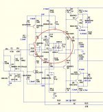
(Below) is my "upgrade". (any "tweaks"/ ideas - are welcome)
PS - any suggestions for the lowest current/cheapest/single amp 8 pin dip available ??
OS
To servo or not ?
All have been banging heads on the HF CFA issues. I know it
absolutely excels at HF/speed.
Esperado got me a goin' on the LF issues. With DC NFB , 20- 500 Hz
either is "all over the board" with offset , differing with both amplitude
and frequency. Using a DC blocking cap solves this issue , but increases
LF THD considerably (also does this on a VFA... to a lesser degree).
OEM's almost universally use a servo with CFA's , only on refined or EF3
VFA's will one be used.
I tried the LT1001 for a CFA servo - I don't like chips on my amps ... 🙁
It worked ... and worked really good.
nV on idle (no signal), under 2mV 20-500hz ,and under 1mv 500hz and up.
So , 1 IC + cap/resistors replaces either a huge DC cap + trimmer or
a trimmer/+ precision divider.
Nothing to trim with the servo - it does the trimmin'. 😀
The CFA behaves differently than a VFA with a servo (like my sansui) ...
much more current at NFB (loads the IC). My study of the CFA servo examples (OEM)
shows they feed the servo to the hi-Z diamond , where a mV or two
at uA's will zero that output. 🙂
Thermal inconsistancies will also have NO effect with the servo ...
point that heatgun at the amp .... 1mV will it be.
(Below) is my "upgrade". (any "tweaks"/ ideas - are welcome)
PS - any suggestions for the lowest current/cheapest/single amp 8 pin dip available ??
OS
Attachments
Last edited:
- Home
- Amplifiers
- Solid State
- CFA Topology Audio Amplifiers