"Our power amplifiers with the fastest devices we can find are not yet fast enough to gives us a 20KHz flat open loop. (Means a flat feedback ratio in all the audio bandwidth)"
Esperado, loop gain bandwidth on my sx-amp extends to 60 kHz - in the write up on my website I show a plot of the loop gain.
Whether or not the wide loop gain band width is the reason difference in sound reported by listeners when comparing CFA with VFA I don't know. PIM was put forward as a reason many years ago, but papers by Cordell and others, including comments by Cherry, have indicated that this cannot be the case.
If we do not have an engineering or scientific explanation (or a plausible hypothesis), we simply have to leave it as subjective preference
The cause of IMD must be different than the cause of THD. According Bob Cordell in the previous thread, the cause of IMD and THD is same. Maybe I must try to reduce THD in the same amp to see if IMD is reduce too.
Its true that both IMD and THD are the result of non-linearity. However with IMD, the crest factor of the signal, particularly when many tones are present, may give different weights to different portions of the transfer function. So a multitone IMD signal, given that it spends a greater proportion of the time at a lower signal level, tends to magnify small signal non-linearity and diminish large signal. This compared to THD which gives more weight to higher level deviations from a straight line and de-emphasises small signal performance.
I believe you have a sim file for it ?"Esperado, loop gain bandwidth on my sx-amp extends to 60 kHz - in the write up on my website I show a plot of the loop gain.
If yes, can you sim bandwitdth at the input of the VAS while in closed loop ?
I'm talking about practical amplifiers, not something in a sim. The LF loop gain in a VFA can be made very high, and the result is lower distortion.
It's like the microprocessor speed wars... Only this time its not Intel vs AMD its CFA vs VFA and loop gain between the topologies being the subject. Both topologies can have very high Loop gain but after a certain level does it really matter?
CFA compensatino and cascodes
To all,
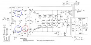
Take a look at the compensation (red encircled) of a NAD319. It uses both input inclusive Miller compensation (whenever possible, always use this one) and shunt compensation as well. I've once simmed this circuit and discovered it was pretty good optimized. Apparently, the engineers at NAD also used a simulator. 🙂
As it is a long time ago, I can't remember whether the shunt compensation was used to stabilize only the Miller loop, or was also used to stabilize the OPS. Remember, some output stages, especially the ones with local FB loops), like a low impedance at HF.
BTW, NAD uses identical trannies in the input cascode (blue encircled). Using Andy's models for the 2SC2240, Zo = 144 Meg, thus even slightly higher than a BC850-2SC3503 combo. 😀 (of course, simmed under the same test condition with Ic = 1mA)
edit: I forgot to mention that there's also a lead-lag compensation at the TIS input, C311 & R325, respectively C313 & R329, clearly meant to stabilize the Miller loop.
There is absolutely no technical reason that would make this statement true, and repeating it also doesn't help.
Shunt lag compensation is probably the worst compensation method. To quote Peter Baxandall "The technique is in all respects sub-optimal". D. Self discusses this at large, and if I recall correctly so does Mr. Cordell, in their books. If you have any arguments as of why shunt lag compensation is preferred for "CFA"s please present your technical arguments.
The only case in which a lead-lag shunt compensation can be really useful is to compensate the Miller loop.
To all,
Take a look at the compensation (red encircled) of a NAD319. It uses both input inclusive Miller compensation (whenever possible, always use this one) and shunt compensation as well. I've once simmed this circuit and discovered it was pretty good optimized. Apparently, the engineers at NAD also used a simulator. 🙂
As it is a long time ago, I can't remember whether the shunt compensation was used to stabilize only the Miller loop, or was also used to stabilize the OPS. Remember, some output stages, especially the ones with local FB loops), like a low impedance at HF.
BTW, NAD uses identical trannies in the input cascode (blue encircled). Using Andy's models for the 2SC2240, Zo = 144 Meg, thus even slightly higher than a BC850-2SC3503 combo. 😀 (of course, simmed under the same test condition with Ic = 1mA)
edit: I forgot to mention that there's also a lead-lag compensation at the TIS input, C311 & R325, respectively C313 & R329, clearly meant to stabilize the Miller loop.
Attachments
Last edited:
Hello ,
Why do you consider that shunt is worst ?Why all the engineers are looking only at the gain in the loop ,that beeing a good criteria ?
The shunt compensations intoduces the smallest group delay and also the highest bandwidth .Make a simulation
I have no idea why shunt compensation would have the "highest bandwidth" and the "smallest group delay".
Shunt compensation is bad for at least two reasons:
- First, it loads the VAS, requiring a much higher current compared to the Miller compensation. Hence, the VAS will have much more distortions.
- Second, shunt compensation does not have the pole splitting property. Because of the missing pole splitting, usually shunt compensation is required to set the dominant pole to a lower frequency compared to Miller compensation, therefore lower HF loop gain, therefore more HF distortions. Obviously, for the same stability margins, shunt has actually a lower bandwidth compared to Miller, not to mention more advanced compensation methods. So much for "highest bandwidth".
The group delay is a measure of the slope of the phase response at any given frequency. I see absolutely no reason why shunt would have a smaller group delay compared to any other dominant pole compensation method. Always recall that audio amplifiers are minimum phase systems, therefore the loop gain and the phase are not independent.
Engineers look for high loop gain because is one of the three methods to lower distortions, beyond high bias (like class A) and distortion cancellation (like in a current mirror loaded LTP).
Sure, it's a nice amp. It has only one minor flaw: the temperature compensation of the OPS. Q137 was mounted free-standing on the PCB. When I glued it to heat sink of Q325, temp. comp. was much better.
Cheers, E.
Cheers, E.
The OPS, yes. But same VAS? Really? wow!
THx-RNMarsh
Yes, the essentials of the VAS are the same, with the exception that the VAS will be push-pull in a CFA, while it will be single-ended or push-pull in a VFA.
I generally prefer a push-pull VAS when using a VFA - see my MOSFET power amplifier with error correction. In fact, it is quite possible that some of the claimed benefits of the CFA architecture derive from the fact that they all use the push-pull VAS, which is superior.
Cheers,
Bob
Actually, there are two distinct classes of CFB amps: one with a passively terminated IPS (i.e. just a resistor at the TIS input) and one with an IPS, terminated with two (controlled) current sources. The latter has a much higher open loop gain, comparable to a VFB amp.
Cheers, E.
Cheers, E.
Last edited:
BTW, NAD uses identical trannies in the input cascode (blue encircled). Using Andy's models for the 2SC2240, Zo = 144 Meg, thus even slightly higher than a BC850-2SC3503 combo. 😀 (of course, simmed under the same test condition with Ic = 1mA)
edit: I forgot to mention that there's also a lead-lag compensation at the TIS input, C311 & R325, respectively C313 & R329, clearly meant to stabilize the Miller loop.
If my eyes don't play tricks, the NAD input stage runs at about 320uA and the cascade at about 2.4mA (not 1mA).
Anyway, this amp confirms what I've already said: "CFA"s are nowhere simpler to compensate compared to a VFA. While in a VFA you can get along (although not necessary optimal) with a single cap Miller compensation, a single gain stage "CFA" usually also requires Miller loop compensation. Unless it has an unusual (and suboptimal) low open loop gain, when you can actually skip completely any explicit compensation.
To those "low gain/large bandwidth" fans, I would kindly remind you that Miller compensation has also the property of lowering the VAS output impedance at HF, hence lowering the HF distortions. That's because the OPS has lower distortions when fed from a low impedance driver.
Actually, there are two distinct classes of CFB amps: one with a passively terminated IPS (i.e. just a resistor at the TIS input) and one with an IPS, terminated with two (controlled) current sources. The latter has a much higher open loop gain, comparable to a VFB amp.
Cheers, E.
Like the one I put the link in #3757?
mcd99uk, I don't think the discussion is about the magnitude of the loop gain.
We've seen very low THD VAF designs using high levels of f/back and CFA design with similar performance with lower levels of feedback.
I think most people now understand the discussion is a lot more nuanced than simply the level of f/back.
We've seen very low THD VAF designs using high levels of f/back and CFA design with similar performance with lower levels of feedback.
I think most people now understand the discussion is a lot more nuanced than simply the level of f/back.
If my eyes don't play tricks, the NAD input stage runs at about 320uA and the cascade at about 2.4mA (not 1mA).
[..]
Indeed, I said: simmed under the same test condition with Ic = 1mA, which, obviously!, refers to the test condition for the BC850-2SC3503 combo, to which a made the comparison. Just apples to apples. See post 3707 for the test setup.
Running the sim with Ic=2.4mA gave the following results for the output impedance of the cascodes:
QBC850 + Q2SC5303: 63.1 Meg
Q2SC2240 + Q2SC2240: 65.5 Meg
So, also with Ic = 2.4mA, the two identical trannies, despite their lower VAF, performs slightly better. That was the only message.
Exactly! A diamond IPS, terminated with CCCSes and tamed by the common mode control loop (CMCL).Like the one I put the link in #3757?
Maybe it is long time ago that designer use symmetrical design (LTP and VAS) for VFA. I used them for my self (DIY) 12-11 year ago. Now, I compare it against CFA.
I agree to make another thread for discuss how to make trade-off decisions (strategy?) in design.
I am not sure how long ago Now means..... I have looked at CFA for much longer than 10-12 years. And, symmetrical designs in audio have been around for a very long time as well as VFA. My personal thinking about 'now' is back to the original days of solid state topologies and even back to the tube designs/topologies. There has been an evolution from mostly N type transistor circuits where-ever possible to truly great complimentary topologies because of the manufacturing processes which has allowed it.
Today, the CFA and VFA in IC mfr'ing are what I call a combo of each best ideas or features to push SOTA. Never-the-less, my observations about the audible qualities of CFA track "Esperado's" descriptions, exactly. Which is why I rarely comment on what he writes.
But, because of portable products (low operating voltages), cascoding cannot be used. That brings the designer back to inherently more linear topologies and other techniques to get distortion lowered. This is where cancellation techniques have been focused on with very good results. Although, little of this matters in audio DIY, it is good to keep up with the times and what others are doing.... job security. If we/us here could start to think about cancellation as an alternative to feedback or an adjunct to it... maybe simpler circuits (lower cost and smaller size?) would result without reducing the parameters we think are important to keep.
Thx-RNMarsh
Last edited:
That's (once more) exactly what i think. But i'm not good enough, or exited enough any more to dig this unfamiliar track. Age is a shipwreck.If we/us here could start to think about cancellation as an alternative to feedback or an adjunct to it... maybe simpler circuits (lower cost and smaller size?) would result without reducing the parameters we think are important to keep.
One word about PSRR and other common mode rejection. I had read a report from L.C. who said adding a cap multiplier to one of his prototypes produced better numbers, but less good results, listening side. I wonder why and i'm interested to correlate this or to get more details. Did somebody else has a similar experience ?
To servo or not ?
All have been banging heads on the HF CFA issues. I know it
absolutely excels at HF/speed.
Esperado got me a goin' on the LF issues. With DC NFB , 20- 500 Hz
either is "all over the board" with offset , differing with both amplitude
and frequency. Using a DC blocking cap solves this issue , but increases
LF THD considerably (also does this on a VFA... to a lesser degree).
OEM's almost universally use a servo with CFA's , only on refined or EF3
VFA's will one be used.
I tried the LT1001 for a CFA servo - I don't like chips on my amps ... 🙁
It worked ... and worked really good.
nV on idle (no signal), under 2mV 20-500hz ,and under 1mv 500hz and up.
So , 1 IC + cap/resistors replaces either a huge DC cap + trimmer or
a trimmer/+ precision divider.
Nothing to trim with the servo - it does the trimmin'. 😀
The CFA behaves differently than a VFA with a servo (like my sansui) ...
much more current at NFB (loads the IC). My study of the CFA servo examples (OEM)
shows they feed the servo to the hi-Z diamond , where a mV or two
at uA's will zero that output. 🙂
Thermal inconsistancies will also have NO effect with the servo ...
point that heatgun at the amp .... 1mV will it be.
(Below) is my "upgrade". (any "tweaks"/ ideas - are welcome)
PS - any suggestions for the lowest current/cheapest/single amp 8 pin dip available ??
OS
Hi OS,
These are good points about the DC servo, and it is an obvious good direction to go in to deal with the offset issues of a CFA. I like DC servos. I have a whole chapter on them in my book. Most DC servo issues are the same for CFA and VFA, except how the correction is injected, as you pointed out. Depending on whether an inverting or non-inverting servo is needed, you may wish to use the two-op amp servo with a dual op amp instead of trying to make a single op-amp non-inverting integrator for the servo (which usually needs 2 caps). I use an audio-grade dual JFET op amp for my servos, such as an OPA2134.
Cheers,
Bob
At least it is a good thing for industrial products, as it avoid fine tuning and minimize the numbers of not perfectly reliable adjustables.These are good points about the DC servo, and it is an obvious good direction to go in to deal with the offset issues of a CFA. I like DC servos.
Hi OS,
These are good points about the DC servo, and it is an obvious good direction to go in to deal with the offset issues of a CFA. I like DC servos. I have a whole chapter on them in my book. Most DC servo issues are the same for CFA and VFA, except how the correction is injected, as you pointed out. Depending on whether an inverting or non-inverting servo is needed, you may wish to use the two-op amp servo with a dual op amp instead of trying to make a single op-amp non-inverting integrator for the servo (which usually needs 2 caps). I use an audio-grade dual JFET op amp for my servos, such as an OPA2134.
Cheers,
Bob
Thanks for comment , Bob.
I'm using the simple inverting mode servo. I don't know if it is a $$
decision .... but both my OEM's use the dual (split) for both channels
(ne5532), inverting -one for each channel.
The OPA211 seems to be the best performance as a upgrade
to the TL071 ... it is so "bombed out" expensive at $8.00 - better
have gold pins.
On both my real amps and on my LT simulations , I DO notice a
slight imperfection in the servo method.
Low frequency , high transient use operation will "fool" the servo for
a couple of AC cycles. No signal =nV of offset , signal "hits" ... then
2mv , then it "settles" to optimum again (<.1mv ).
This effect is much less as you reach HF.
This "effect" also happens (EXACTLY) on my sansui Z3900 receiver.
By esperado - At least it is a good thing for industrial products, as it avoid fine tuning and minimize the numbers of not perfectly reliable adjustables.
And audiophile products (It is used frequently). It even
allows for optional capacitor-less input coupling on the High-Z diamond.
A "true DC" amp. Depending on the ratio of servo R to input
R , correction will be done even with 100's of mV's input signal offset.
OS
- Home
- Amplifiers
- Solid State
- CFA Topology Audio Amplifiers