LT1166
Hi Bob,
Yes, it is.
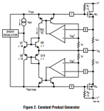
But.....by translinear I suppose you mean that the circuit obeys exactly a geometric mean rule (also known as constant product rule). If that was indeed the case, then the circuit would be vulnerable to Vbe mismatches. Fortunately that isn't the case, as I have shown here (see graph, red curve), the LT1166 does not obey the geometric mean rule. Instead, the current of the inactive OP device is always held above a safe minimum level, according to my simulation about 40mA (or 1/3 of Iq). With such a minimum current, the voltage drop across the sensing resistors, typically 0.22 Ohm, is always large enough to cope with some Vbe mismatch.
Probably you have missed it, but that was the tenor of my previous comments.
Cheers, Edmond.
Hi Bob,
Hi Edmond,
I looked at the innards of the LT1166 SPICE model several years ago. I don't remember the details, but I'm pretty sure it is fairly well-behaved
Yes, it is.
That's right and I didn't say the LT1166 is subject to above tendency. Instead, it is (to a certain extent) quite insensitive to Vbe mismatches. Why? See below.and does not have a tendency like you described even when there are slight Vbe mismatches.
Again, you are right. It is a clever circuit (that is, as far as bias generator section is concerned).It is a fairly clever translinear circuit.
Cheers,
Bob
But.....by translinear I suppose you mean that the circuit obeys exactly a geometric mean rule (also known as constant product rule). If that was indeed the case, then the circuit would be vulnerable to Vbe mismatches. Fortunately that isn't the case, as I have shown here (see graph, red curve), the LT1166 does not obey the geometric mean rule. Instead, the current of the inactive OP device is always held above a safe minimum level, according to my simulation about 40mA (or 1/3 of Iq). With such a minimum current, the voltage drop across the sensing resistors, typically 0.22 Ohm, is always large enough to cope with some Vbe mismatch.
Probably you have missed it, but that was the tenor of my previous comments.
Cheers, Edmond.
Not necessarily. Translinear just means that you make a circuit with one or more loops of diodes or BE-junctions, such that the number connected clockwise in each loop equals the number connected anticlockwise, and take advantage of the exponential voltage to current transfer to make some nonlinear function. That nonlinear function could be a product, a geometric mean, a harmonic mean, the 33rd power root of the product of I1 to the twelfth power and I2 to the twentyfirst power, or anything in between.
Hi Bob,
I suppose you mean that the circuit obeys exactly a geometric mean rule (also known as constant product rule). If that was indeed the case, then the circuit would be vulnerable to Vbe mismatches.
Cheers, Edmond.
This is not true, Vbe mis-match in this context is a simple scaling error. Delta-Vbe with current ratio factors out the absolute Vbe, i.e. 10X the current is an ~60mV delta for any Vbe. If you normalized those plots I don't think the difference is that large.
Constant product biasing works fine.
Hi Scott,
I agree with Edmond on this one. It is not the VBE mismatch inside the translinear loops that could cause a problem, but the VBE mismatch in the input stages of the op-amps of the voltage to current converters. The LT1166 uses resistors to sense the current, rather than injecting the currents straight into the translinear loop.
Maybe Linear Technology introduced a deliberate offset in the right direction in those op-amps. If so, that could explain why it has a harmonic-mean-like behaviour while its datasheet shows a product rule translinear circuit.
Regards,
Marcel
Last edited:
Hi Scott,
I agree with Edmond on this one. It is not the VBE mismatch inside the translinear loops that could cause a problem, but the VBE mismatch in the input stages of the op-amps of the voltage to current converters. The LT1166 uses resistors to sense the current, rather than injecting the currents straight into the translinear loop.
Maybe Linear Technology introduced a deliberate offset in the right direction in those op-amps. If so, that could explain why it has a harmonic-mean-like behaviour while its datasheet shows a product rule translinear circuit.
Regards,
Marcel
Actually you are agreeing with me, if there is some sleight of hand in the op-amps fine, the operation of the current mirrors is basic physics.
“The earth's rotation will slow within days and stop for several days just prior to the pole shift. This is when you and your loved ones should be situated at your safe location.”
Some solid advice there! :0
Some solid advice there! :0

“The earth's rotation will slow within days and stop for several days just prior to the pole shift. This is when you and your loved ones should be situated at your safe location.”
Some solid advice there! :0
He is wrong, the pole shift is not that time, but different time. The day earth is slowed doesn't shift the poles.
The slowest at first day, 1 day is ~9000 hours. The calculation is complex though...
 When that time happened just make good hide and run away from him.
May be LT is just trying to make similar chip like pioneer do.
Pioneer itself is not continuing nonswitching project, may be the best in comercial is pioneer Type1, it increasing nonswitch distortion, but better drop curve.
Last edited:
Hi Marcel,
Exactly.
BTW, this circuit is quite immune to a moderate input offset (1mV or so).
Cheers, E.
Hi Scott,
I agree with Edmond on this one. It is not the VBE mismatch inside the translinear loops that could cause a problem, but the VBE mismatch in the input stages of the op-amps of the voltage to current converters. The LT1166 uses resistors to sense the current, rather than injecting the currents straight into the translinear loop.
Exactly.
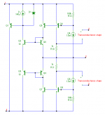
I've simmed the simplified circuit of the LT1166 (see below) and it seems that the harmonic-mean-like behavior is a inherent property of the circuit, thus without any deliberately added offset. So, somewhere this 'offset' has been hidden. Where exactly, I haven't figured out yet.Maybe Linear Technology introduced a deliberate offset in the right direction in those op-amps. If so, that could explain why it has a harmonic-mean-like behaviour while its datasheet shows a product rule translinear circuit.
Regards,
Marcel
BTW, this circuit is quite immune to a moderate input offset (1mV or so).
Cheers, E.
Attachments
Hi Marcel,
Cheers, E.
BTW I assumed we are talking about IC's typical delta Vbe's would be in the 250uV max region, I would not try to make this exact thing discretely.
What happens at the equator during the pole shift?
And be sure to hold on to something.
-RM
And be sure to hold on to something.
-RM
Last edited:
Hi Bob,
Enjoy this day!
Cheers, Edmond.
Thanks!!!
I didn't know you knew.
Cheers,
Bob
BTW I assumed we are talking about IC's typical delta Vbe's would be in the 250uV max region, I would not try to make this exact thing discretely.
Hi Scott,
>250uV
Indeed, something of that order.
>discretely
In case of a geometric mean bias, even an offset of 250uV might already cause trouble: Suppose Iq = 100mA and RS = 0.22 Ohm and the active OP device draws 10A, then the inactive OP device should draw 1mA. IOW, 220uV across RS. With 250uV offset in the 'safe' direction, the latter current will rise to ca. 2mA, while in the ''wrong' direction it means havoc (as 250uV > 220uV).
Cheers, E.
I have close relations with the NSA! 😀Thanks!!!
I didn't know you knew.
Cheers,
Bob
Cheers, E.
They'll have to turn 180° their deckchairs and hammocks for a good sleep.What happens at the equator during the pole shift?
Oh, please, i'm lost somewhere in the country, with a bottle of Champagne for Bob, and my GPS is broken. Can-you ask them where i am ?I have close relations with the NSA! 😀
.
Last edited:
Hi Christophe,[..]
Oh, please, i'm lost somewhere in the country, with a bottle of Champagne for Bob, and my GPS is broken. Can-you ask them where i am ?
Right now, according to the NSA, you are busy with an ABC.....XYZ speaker listening test in Café Charbon, 109 Rue Oberkampf, Paris, France. They send me this picture. 😉
Cheers, E.
Attachments

Last edited:
Hi Scott,
>250uV
Indeed, something of that order.
>discretely
In case of a geometric mean bias, even an offset of 250uV might already cause trouble: Suppose Iq = 100mA and RS = 0.22 Ohm and the active OP device draws 10A, then the inactive OP device should draw 1mA. IOW, 220uV across RS. With 250uV offset in the 'safe' direction, the latter current will rise to ca. 2mA, while in the ''wrong' direction it means havoc (as 250uV > 220uV).
Cheers, E.
Yes, offset in the sense amp is bad I meant in the translinear loop even 18mV means you have 1/2 of what you thought but it can't fail from sign reversal.
I've simmed the simplified circuit of the LT1166 (see below) and it seems that the harmonic-mean-like behavior is a inherent property of the circuit, thus without any deliberately added offset. So, somewhere this 'offset' has been hidden. Where exactly, I haven't figured out yet.
How did you model the op-amps? Ideal controlled sources with huge gain?
The base currents of Q7 and Q8 subtract Iref/hFE from the sensed current, so maybe it is simply the finite DC current gain of Q7 and Q8 that does the trick. Does it still work with ideal voltage followers driving Q7 and Q8? Or with the BF of the transistors increased by a few decades?
Last edited:
Hi Marcel
They were simple synthetic transconduction stages (VCCS) with a gain of 1.5mA/V (the same as in the real chip). Please see pic below. (D1, R12 & R13 have little effect. They only are meant to avoid convergence issues. Node numbers correspond with pin numbers of the LT1166)
Cheers, E.
How did you model the op-amps? Ideal controlled sources with huge gain?
They were simple synthetic transconduction stages (VCCS) with a gain of 1.5mA/V (the same as in the real chip). Please see pic below. (D1, R12 & R13 have little effect. They only are meant to avoid convergence issues. Node numbers correspond with pin numbers of the LT1166)
Beta does have some effect, but not that large. When I increase beta to 10000, the minimum drain current (of the OP device) is half as large, but still much larger than expected form a true geometric mean bias control.The base currents of Q7 and Q8 subtract Iref/hFE from the sensed current, so maybe it is simply the finite DC current gain of Q7 and Q8 that does the trick. Does it still work with ideal voltage followers driving Q7 and Q8? Or with the BF of the transistors increased by a few decades?
Cheers, E.
Attachments
- Home
- Amplifiers
- Solid State
- CFA Topology Audio Amplifiers