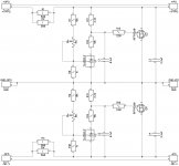
Shuntie is finalized
I have tested the Shuntie. Initial test has shown - using zeners there was not really a good idea. The loop gain becomes too high and the regulator oscillated at around 20KHz - not violently, low amplitude, but not good.
I have replaced all the zeners with appropriate resistors - now it works perfectly.
With the front-end attached, the regulator's power dissipation is ok, although I use the small local heatsinks on top of IRFP240/9240 - just in case.
I will publish the updated schematic and PCB soon.
Cheers,
Valery
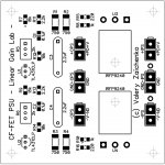
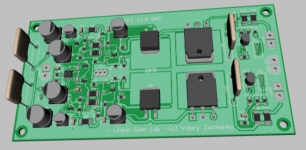
PSU - final version
Fully tested now. For high-current IPS (28mA in total in my case), R1-R4 optimal value is 750R each. For the lower current IPS (8-12mA in total), the best value is 1K. Trimmers R5, R6 allow setting the exact output voltage (+/-50V DC in my case). Small local heatsinks are used on top of the MOSFETs for better heat dissipation. Soldering the second channel PSU now.
Gerbers are available on request.
Cheers,
Valery
Attachments

Mine are leaving Hong Kong right now.
Wow! I like it 🙂 Makes a lot of sense combining them

Is this better to run on a Slewmaster or TubSoMo output board?
I have tested with both. Well, if you don't need too much power or don't plan to apply too much load (down to 2 ohm or something at that level) - TubSuMo is an excellent-sounding yet simple OPS. It also shows the lowest phase shift at 20KHz = 2.2 degrees.
5-pair IRFP-based SlewMonsters provide enormous current capability at the output - up to the level of some 75A in a short impulse 😱 Handling virtually any load that makes practical sence, if the power supply is good enough. Measured phase shift at 20KHz is 3.3 degrees, which is also very good. Slightly lower THD at 1KHz (although slightly higher at 20KHz), but very low in both cases anyway. Slightly sharper 20KHz square wave response.
In fact, all the key qualities are very close in both cases - I can't hear any audible difference, both options sound excellent at normal load (6-8 ohm).
Cheers,
Valery
I'll have to try it with both outputs myself I guess. I'll have enough boards to build up both versions to test. I've never built a FET Slewmonster yet. That might be a good project if things ever slow down.I have tested with both. Well, if you don't need too much power or don't plan to apply too much load (down to 2 ohm or something at that level) - TubSuMo is an excellent-sounding yet simple OPS. It also shows the lowest phase shift at 20KHz = 2.2 degrees.
5-pair IRFP-based SlewMonsters provide enormous current capability at the output - up to the level of some 75A in a short impulse 😱 Handling virtually any load that makes practical sence, if the power supply is good enough. Measured phase shift at 20KHz is 3.3 degrees, which is also very good. Slightly lower THD at 1KHz (although slightly higher at 20KHz), but very low in both cases anyway. Slightly sharper 20KHz square wave response.
In fact, all the key qualities are very close in both cases - I can't hear any audible difference, both options sound excellent at normal load (6-8 ohm).
Cheers,
Valery
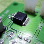
I received my boards today. Almost done but I'm stumped on the IRFs. How do you solder them to the board?
OK, then just solder the pins and the edge of the plate - just make sure that edge is warmed properly together with the PCB trace under it - solder will flood that area just by itself as soon as it's liquid enough.
Attachments
All soldered up and ready for testing. I had to make a few substitutions. I didn't have 220p SMD so that is a through hole part and I didn't have 22R SMD so I paralleled two 47R. Hopefully that will be close enough.
Still need to clean up the flux and test for continuity and shorts but should be testing in the morning.
Blessings, Terry
Still need to clean up the flux and test for continuity and shorts but should be testing in the morning.
Blessings, Terry
Attachments

Looks cool! For initial standalone testing, better connect PD+, ND- and NFB all together, without resistors. You can check the VAS current, measuring the voltage over R21, R24.
All soldered up and ready for testing. I had to make a few substitutions. I didn't have 220p SMD so that is a through hole part and I didn't have 22R SMD so I paralleled two 47R. Hopefully that will be close enough.
Still need to clean up the flux and test for continuity and shorts but should be testing in the morning.
Blessings, Terry
Nice work guys!OK, then just solder the pins and the edge of the plate - just make sure that edge is warmed properly together with the PCB trace under it - solder will flood that area just by itself as soon as it's liquid enough.
I can't follow🙁
I must find a sponsor😀
- Status
- Not open for further replies.
- Home
- Amplifiers
- Solid State
- CF-FET V2.0 front-end - going high-tech (SMD)