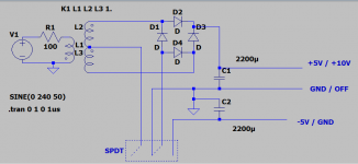
I am trying to build a power supply that has the capability to change voltage and curent via an adoino. But first do I struggle with the problem on how I can change output from +-5V with center tab and to 0-10V without center tab.
I have found some sort of clumsy way for enabling and disabling the center tab, but there have to be a better way. I have searched here and on google, but with no luck. Hope you please will help.
I have found some sort of clumsy way for enabling and disabling the center tab, but there have to be a better way. I have searched here and on google, but with no luck. Hope you please will help.
Attachments
Just hard wire the entire +/-5VDC supply, and switch the DC output connections instead.
Last edited:
Sounds logical but how do I do that, sorry are a noob.Just hard wire the +/-5VDC supply, and switch the DC output connections instead.
Sounds logical but how do I do that, sorry are a noob.
You'll have three output lines: +5V, common, and -5V.
For +/-5V, you select all three lines to the proper 3 output connections.
For +10V, you select the +5V and the -5V lines to the proper 2 outputs,
and leave the center tap line open.
What is it you are powering with the supply?
Last edited:
Oh so -5V do just act as ground and +5V has a potential of 10 over ground?You'll have three output lines: +5V, common, and -5V.
For +/-5V, you select all three lines to the proper 3 output connections.
For +10V and 0V, you select the +5V and the -5V to the proper 2 outputs,
and leave the center tap line open.
What is it you are powering with the supply?
I hope to power some IC's on a test board, but want to build the psu as a more permanent sollution, so I can used to act as 1.2V battery or even less.
For +10V, the ground/common line is floating/open, and you connect the load between +5V and -5V.
Connect the -5V to the powered circuit's ground, and the other line will be at +10V relative to ground.
If it's for lab use, I'd not switch anything and just have 3 output terminals, connecting externally as needed.
That's how lab supplies are normally made, usually with tracking between positive and negative voltages.
Yours will track automatically, since it's just one supply circuit. You probably won't need the two voltages
to be unequal in most uses. Do you need to vary the voltages, or just choose between +/-5V and +10V?
Many variable regulators won't go down to very low voltages without some circuit tricks because of
an internal reference voltage. If you don't use regulators, there will be significant ripple/noise.
.
Last edited:
I think you are 100% right, and if I should need some sort of difference, I can just make an voltage divider. 🙂If it's for lab use, I'd not switch anything and just have 3 output terminals, connecting them as needed.
That's how lab supplies are normally made, usually with tracking between positive and negative voltages.
Yours will track automatically, since it's just one supply circuit. You probably won't need the two voltages
to be unequal in normal use.
Do you know what I shall search for when looking for a way to make the psu variable in both voltage and current?
Maybe there is a slight problem in just hard wire the connection, the capacitors do then connect in series and loose half of it's capacity.
Do you know what I shall search for when looking for a way to make the psu variable in both voltage and current?
That's going to be a much more involved project. Have you considered buying a commercial power supply
all ready to go? Basic Chinese supplies are about the cost of the parts you would have to buy.
This is a basic one, maybe good enough.
Dual-Output Adjustable Linear Regulated Power Supply Kit | eBay
Yes I know, but it is mostly for me to learn by, not so much because I need one. As you say, I could propperly buy one for $60 that will work perfect. 🙂That's going to be a much more involved project. Have you considered buying a commercial power supply
all ready to go? Basic Chinese supplies are about the cost of the parts you would have to buy.
This is a basic one, maybe good enough.
Dual-Output Adjustable Linear Regulated Power Supply Kit | eBay
Yes I know, but it is mostly for me to learn by, not so much because I need one.
As you say, I could propperly buy one for $60 that will work perfect. 🙂
Ok, then check this out.
YouTube
Thanks a lot! I'll do that now🙂Ok, then check this out.
YouTube
But am I right in that if I hard wire my schematic from first post, to deliver +-5V, that the capacity will be halved when using the psu as 0-10V ?
Thanks a lot! I'll do that now🙂
But am I right in that if I hard wire my schematic from first post, to deliver +-5V, that
the capacity will be halved when using the psu as 0-10V ?
The maximum current output will be the same, since the two supply outputs are used in series.
The ripple voltage will be doubled on the 10V connection, compared to the 5V, since the ripple voltages
add also. But it's the same % of the DC level as for the 5V. Both the voltage and the ripple double.
Last edited:
Yes taken out from the transformers data, will it do as you say. What I think about the capacitors is that when the center lead is used, the capacitors do all charge and discharge normally with full capacity. While if the -5V is used as ground, there will be two capacitors in series and therefore do 2X2200uF converted to 1X1100uF, and therefore have less capacity to reduce ripples.The maximum current output will be the same, since the two supplies are used in series.
The ripple voltage will be doubled on the 10V connection, compared to the 5V,
since the ripple voltage adds also. But it's the same % of the DC level as for the 5V.
Yes taken out from the transformers data, will it do as you say. What I think about the capacitors is that when the center lead is used, the capacitors do all charge and discharge normally with full capacity. While if the -5V is used as ground, there will be two capacitors in series and therefore do 2X2200uF converted to 1X1100uF, and therefore have less capacity to reduce ripples.
Think of two equal resistors connected in series, between the +5V and -5V, with no connection to the ground.
The middle point of the resistors is at 0V by symmetry. Equal current flows in each resistor,
since they are in series, so there are equal voltage drops across each resistor. The center point must be at 0V.
Then the center point of the resistors can be connected to ground (also at 0V) with no change in the
circuit's operation. Now there are separate loads on each 5V output, but the circuit doesn't know any difference.
The ripple does not change, just the way you look at it.
Last edited:
Okay, great explanation! Thanks! 🙂Think of two equal resistors connected in series, between the +5V and -5V, with no connection to the ground.
The middle point of the resistors is at 0V by symmetry. Equal current flows in each resistor,
since they are in series, so there are equal voltage drops across each resistor. The center point must be at 0V.
Then the center point of the resistors can be connected to ground (also at 0V) with no change in the
circuit's operation. Now there are separate loads on each 5V output, but the circuit doesn't know any difference.
The ripple does not change, just the way you look at it.
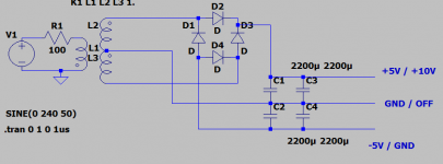
So if I understand you correct, do the ground act as Null no matter that I only use +5V and -5V? That I get +10V out because there are 10V difference between the two leads, no matter that they both are connected to ground?
I have made a new drawing, that illustrate what I think you mean.
Attachments
Okay, great explanation! Thanks! 🙂
So if I understand you correct, do the ground act as Null no matter that I only use +5V and -5V? That I get +10V out because there are 10V difference between the two leads, no matter that they both are connected to ground?
There are only voltage differences, that is, the difference between two circuit nodes.
There is no "absolute " 0V; we just define a convenient node as 0V, and measure
other circuit nodes with respect to it.
The power supply "ground" node does not have to be our reference node.
If we ignore it and leave it unconnected, any other node can be the reference 0V node,
such as the former -5V node. If that node is now defined as 0V, then the former +5V node
will measure +10V wrt the new 0V node. If we measure the former "ground" node,
it will be at +5V potential wrt the new 0V node.
You build the supply with NONE of the connections going to ground. What you are calling ground is the common within the circuit. You simply put three terminals - insulated - on the panel of your supply, +5, -5, and C. Then you connect clip wires to it however you need.
You can connect ONE terminal to ground in your unit under test. So if you need +/-5, connect C to ground. If you need +10, connect -5 to ground. If you need -10, connect +5 to ground. The three terminals float electrically.
Imagine a 9v battery in your hand. Neither end is "ground" until you connect ground to one end.
I recommend making yourself call the common in your supply "common" rather than "ground". Save "ground" for the unit you are working on.
Would it not be best if I just avoid any ground at all and make it floating?You build the supply with NONE of the connections going to ground. What you are calling ground is the common within the circuit. You simply put three terminals - insulated - on the panel of your supply, +5, -5, and C. Then you connect clip wires to it however you need.
You can connect ONE terminal to ground in your unit under test. So if you need +/-5, connect C to ground. If you need +10, connect -5 to ground. If you need -10, connect +5 to ground. The three terminals float electrically.
Imagine a 9v battery in your hand. Neither end is "ground" until you connect ground to one end.
I recommend making yourself call the common in your supply "common" rather than "ground". Save "ground" for the unit you are working on.
Do that not add some safety for the DUT?
- Home
- Design & Build
- Construction Tips
- Center tab on / off or, from +-5V to 0-10V