Hmm maybe I should drop my small supply and build a powerful one, I mean one that I can use while building my amplifier?Most lab supplies are built with two floating supplies in one cabinet, more flexible and no disadvantages.
Lets say a psu that can be used to power op to 200W 8Ohm or 800W 2Ohm, Have not yet use for a monster like that, but why not build one that can be used all the way and beyond... stupid idea?
Hmm maybe I should drop my small supply and build a powerful one, I mean one that I can use while building my amplifier?
Lets say a psu that can be used to power op to 200W 8Ohm or 800W 2Ohm, Have not yet use for a monster like that, but why not build one that can be used all the way and beyond... stupid idea?
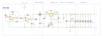
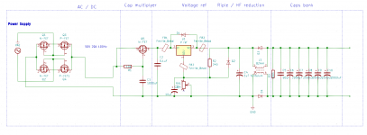
You could use a Variac to vary the AC line voltage, then connect it to a power transformer
and supply circuit like in the earlier schematic. There's even a pcb for that.
Universal Power Supply – diyAudio Store
Thanks a lot, but I think it could be more fun to build it myself from the schematic you did send and then add Dave's sustainability to that circuit. I know that my end result properly is less great then by buying, but I have more fun🙂Sure, you could use a Variac to vary the AC line voltage, then connect to a power transformer
and supply circuit like in the earlier schematic. There's even a pcb for that.
Universal Power Supply – diyAudio Store
Most op amps can only output around 10mA.
Most 3 terminal regulators have around 1A output, so it would need a "boost" device to carry the large current.
Most 3 terminal regulators have around 1A output, so it would need a "boost" device to carry the large current.
Last edited:
You are great, that you keep helping me! 🙂Most op amps can only output around 10mA.
Most 3 terminal regulators have around 1A output, so it would need a "boost" device to carry the large current.
What if I use comparators instead of op-amps?
Do R2 and R5 not let the amps go around the op-amp, so not to destoy the op-amps?
The op amps only work on around a 15V power supply, so the most the current through the resistors
could be is 15/R. For R=1k, that would be 15mA.
could be is 15/R. For R=1k, that would be 15mA.
May I please ask you to present a booster on a silver plate? 🙂 I have no idea on type of booster, function or implementation nor connecting.
So I am fare lost here!
So I am fare lost here!
May I please ask you to present a booster on a silver plate? 🙂
I have no idea on type of booster, function or implementation nor connecting.
So I am fare lost here!
Here's one idea for a higher current linear regulator, there are many variations.
Creating a high current LM317 regulator | All About Circuits
Last edited:
Funny, the top schematic, looks a lot like my solution.Here's one idea for a higher current linear regulator, there are many variations.
Creating a high current LM317 regulator | All About Circuits
But are all the schematics not thought to be used after the rectifier?
The solution I try to use should almost eliminate any voltage drop and thereby reduce heat a great deal.
But are all the schematics not thought to be used after the rectifier?
Yes, only DC input. A linear supply will have losses since the regulator needs a certain minimum voltage drop,
and also has to accommodate variations in AC line voltage. That's why switching supplies can be so much
more efficient.
Yes voltage drop can't be totally avoided but almost, I think that "my" rectifier do not drop anything significantly.Yes, only DC input. A linear supply will have losses since the regulator needs a certain minimum voltage drop,
and also has to accommodate variations in AC line voltage. That's why switching supplies can be so much
more efficient.
I have also tried to build it so that it can be used for both types of power supplys.
By the way I have found a 95% effective torroid🙂
Yes voltage drop can't be totally avoided but almost, I think that "my" rectifier
do not drop anything significantly. By the way I have found a 95% effective torroid🙂
But that's not a high current rectifier, op amps are low current devices.
Transformers typically lose 5%-10% of the power.
You are completely right, would you just use a diode bridge instead and live with the voltage drop?But that's not a high current rectifier, op amps are low current devices.
Transformers typically lose 5%-10% of the power.
Is there a way to lower the heat dispensation?
You are completely right, would you just use a diode bridge instead and live with the voltage drop?
Is there a way to lower the heat dispensation?
Synchronous rectifier (transistors used for the rectifiers). Example:
http://www.ti.com/lit/wp/snva595a/snva595a.pdf
Last edited:
Wary interesting, I'd try to read it trough several more times and try to use some of it🙂Synchronous rectifier (transistors used for the rectifiers). Example:
http://www.ti.com/lit/wp/snva595a/snva595a.pdf
This circuit has some small mistakes and don't supposed to work with 20 A, it's several amperes maximum, if we make same change (connect power line to mosfet).Is this circuit usable for 50V 20A 100Hz?
If TS don't knows what to do with such cirquit then I recommend find something else.
If TS needs just several amperes regulated voltage then I recommend use only integral regulator, like LT1083.
I'm afraid that rectifier part, q1-q4, cant't work if AC voltage will be higher than 15-20 V.I have read the pdf and several other texts about rectifier and think I have arrived to the conclusion that MOSFET's with a build in Schottky diode, should give least voltage drop and most stable rectifying.
There is "ideal diode driver" IC for such type active rectifiers, LTC4320 for examole - it works up to about 70 V (I don't remember exact value).
Easy way of use this circuit - change Q1-Q4 to Shottky diodes (for large currents, >3-4 A they need radiator cooling).
Last edited:
Thanks! Sounds wary interesting, sorry for not replying before. Do the rest look like it could work and effective lower ripples?I'm afraid that rectifier part, q1-q4, cant't work if AC voltage will be higher than 15-20 V.
There is "ideal diode driver" IC for such type active rectifiers, LTC4320 for examole - it works up to about 70 V (I don't remember exact value).
Easy way of use this circuit - change Q1-Q4 to Shottky diodes (for large currents, >3-4 A they need radiator cooling).
- Home
- Design & Build
- Construction Tips
- Center tab on / off or, from +-5V to 0-10V