Thought I sent it. There were 3 or so versions based on output current capability. The higher units had 50 ohm resistors for R3/4; 4.7ma current sources and 2N5321/23 outputs.
Cello never deleted a product during their 15 year lifetime. You could get an Audio Palette in 2000 (or at least order one - they went out of business midyear)
Being a small operation, they also built their product in "batches". So you wanted a Palette, they checked their inventory, let you know the wait time and maybe ordered the necessary parts. Problem with this - as any manufacture with product longevity ran into - was parts obsolescence - especially with semiconductors. One of their mainstay amp boards was the OTA (Output Transconductance Amplifier) which in conjunction with the VF (Voltage follower) used in all their preamps - and the effective circuit in all their amps. OTA Went thru revisions up thru -6; VF thru-3. Paul Jayson told me he spent a lot of time over the years with a Tek curve tracer identifying suitable replacements. They used an AP machine for development and unit testing.
Attachments
That is exceptionally helpful Charles! The OTA2 is not a totally straightforward design - still getting my head around the knot of transistors Q3,4 and 6. The VF is essentially a diamond buffer.
I've been working up a discrete version ( just simulated at this stage) of the National circuit, with Charles's modified boost values. This is based on the Quad-Eight AM10 discrete opamp. That is such an iconic design and seems to work exceptionally well. It runs from +/-28V rails, and clips at a hair over +/- 26V peak-peak, so 28dBu. Output noise over a 20kHz bandwidth, with 1k summing resistors, is 12.5uV (and with 10k summing resistors just 1uV more at 13.5uV).
The original NPN's (2N4249) and output devices (2N2102 and 2N4036) for the AM10 (sometimes called the OM10) are somewhat astonishingly still available from the usual suppliers. The PNP's (TIS98) were obsoleted by OnSemi alas, so the simulation uses BC546B's instead, which seem to work pretty well.
Compensation capacitors need to be tweaked in value or omitted depending depending on where the opamps are in the circuit to tailor the RF response. With controls centered (in the simulation) it is ruler flat to 100kHz with the -3dB at 250kHz.
I've also adapted a published diamond buffer design that is rather more complicated than the Palette one. That also runs from 28V rails, and produces exceptionally low distortion into 400 ohms (with chunky output transistors) and less than 1uV of output noise, simulated.
To understand what I'm banging on about you need to reference the National Audio handbook 1977 that Charles kindly pointed us towards. Downloadable free if you search.
This is going to end up being an interesting project for sure.
Craig
Can´t get my head around how the summing amp works, any detail on this Charles?
(The Rane/ Rod Elliot constant Q equalizer circuit makes more sense to me, but I would love to know all the details.)
Is seems that the different filter sections had different values of R3 ( output series resistor) AND they seem to have different gain in their respective band according to the values fo R2/R1, so that should almost do it.
...But the previously attached block diagram does not reveal any shunting resistor before the + input of the OTA2 in the summing amp an also no feedback resistor to a - output or something that would be expected in a nromal summing amp.
So are the different R3 values and actual gain in the filters the only thing responsible for the weighting of the diffenret gain range of the bands within themselves or what?
I've been looking at this too. A feedback resistor of 10 ohms makes no sense. The way this type of circuit works is that summing is done into the positive input of the opamp, and the negative input has to have a gain of precisely one - so the output resistor to the overall input has to equal the feedback resistor. So in this case, 2k. So the feedback resistor ought to be 2k, not 10 ohms.
Next look at the output resistors of the input amp - two ten ohm resistors in parallel. So I think that the 10 ohm resistor in the feedback ought to be in parallel to R17, and the 205 ohm resistor ought to be on the inverting input of the opamp to ground. That is needed to set the overall gain with controls centered at one. It is usually equal to the parallel resistance of the R3's in the filter circuit. That is actually 170 ohms, but the value on the schematic is 205 ohms - probably found by tweaking.
The other point is that OTA-1 (Operational Transconductance Amplifier) has a very high output resistance (taken from the collectors in OTA-1), and is therefore a current driver, So the output resistors cannot go to an opamp input - particularly OTA-2, which has JFET inputs and an exceptionally high input resistance. So there has to be another resistor to ground somewhere to ensure that the current has somewhere to go. So there is a possibility that the 205 ohm resistor is supposed to be on the positive input to provide a ground return. Or the 10 ohm resistor might go there with the 205 ohms on the negative input to ground to set the 0dB point.
This is just speculation of course - but the EQ circuit as drawn makes no sense.
Craig
There also has to be a bit of hidden detail. There are blocks that are specified as OTA-2 + VF. OTA-2 also has a high output impedance. So there has to be a resistor to ground between OTA-2 and the diamond buffer VF that sets the overall gain of that block.
Craig
Craig
More progress. This relates to noise, and particularly to the National design (Chapter 2.17 of the 1977 National Semiconductor Audio Handbook). The design as presented in that has rather high value resistors, and that compromises noise performance. The integrated output noise of each filter is 21uV over a 20kHz bandwidth, which is very high.
The summing resistors are 100k - which produces 5.7uV for each resistor. Because these to noise sources are not correlated the add in a sum of square way giving a total per channel of 22uV.
These are squared, added (10 channels) and rooted to give a final output noise of 69.6uV. Over the six Palette channels it is 53.9uV. Both these numbers are pretty noisy.
Anyhow the design can be tweaked to give even lower noise. By reducing the pot from 100k to 10k, the other resistors scale more or less proportionally, and the capacitors go up by a factor of ten. The proviso is that Burwen noticed that you need to reduce the resistors further to reduce the noise contribution of the 5kHz and 20kHz filters. That is absolutely true, and for those bands I've reduced the potentiometers to 1k. That puts a rather heavy burden on the amp driving those bands. But the OM10 works like a champ, producing 27.5dBu at 0.007% distortion.
The net effect is that the output noise over a 20kHz bandwidth, with filters flat, is
20Hz 2uV
120Hz 2.4uV
500Hz 3uV
2kHz 4.3uV
5kHz 1.6uV
20kHz 2.2uV
That gives a noise (squaring, adding and rooting) of 6.7uV; However to those must be root added to the noise from the (now) 10k summing resistors - 1.8uV to give
20Hz 2.7uV
120Hz 3uV
500Hz 3.5uV
2kHz 4.7uV
5kHz 2.4uV
20kHz 2.8uV
These are then squared, added and rooted to give a final output noise of 8.0uV. Burwen's target for his original full-of-opamps Cello Palette was a final output noise of less than 10uV, So it looks like the design is heading in that sort of output noise. At least in simulation, that is!
The noise could be reduced somewhat to get closer to the 6.7 uV mentioned above by reducing the summing resistors to say 3k to give an output noise of 7.1uV. That is nearly 18dB quieter than the original National implementation.
Now we're off to Australia for a month. Which means much to your relief I'll shut up come Monday for a month.
Craig
Last edited:
It has bucketed down for quite a while. My daughter and her husband live in NSW, so they have had the full force of the endless downpour. Well above flood level though.
But that is just half of the problem - in spite of being triple vacced they both currently have a dose of Covid. So the first few days we will have to say in a hotel rather than at their place, We've both had it, and it was just like a dose of bad cold. We've very recently had our fourth shot, so hopefully we'll be pretty immune at the moment.
But that is just half of the problem - in spite of being triple vacced they both currently have a dose of Covid. So the first few days we will have to say in a hotel rather than at their place, We've both had it, and it was just like a dose of bad cold. We've very recently had our fourth shot, so hopefully we'll be pretty immune at the moment.
Because I can't leave well alone, I carried out a much more accurate simulation using http://www.spectrum-soft.com/index.shtm now downloadable free.
Without going into the nuts and bolts, the 10-band described in the National article, gives 38.7uV, filters flat, 20kHz bandwidth.
With Charles' boost and cut levels for his version of the Palette preamp, the noise output of the pure National implementation is not much less, at 33.5uV. My improved National design gives 7.1uV (13.8dB quieter).

We're back from that month in Australia. Coincident with us arriving in Sydney and then Newcastle, the sun came out and there was not a drop of rain. So all the wet weather gear we packed stayed packed! Trowel loads of factor 50+ sun block though.Better bring your swimming gear as we're a 'bit wet' just now!
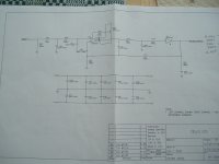
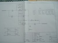
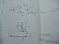
Here are the applicable schematics for the EQ portion of the Palette PREAMPLIFIER. Hope you can read them OK.
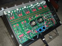
And a pic of the EQ PC board. Filters are along the top half. Input and output bottom left. Post-regulator bottom middle and overvoltage protection lower right.
Rest of the pre is on a second board
Didn't realize till now that you had some questions about my earlier schematic postings. Will try to figure this out.
Attachments

Last edited:
Superb Charles - thanks! Just one question - shouldn't C15/C16 scale with frequency too?
Cheers
Craig
Cheers
Craig
OK - simulation suggests, for C15 (+C16)
20Hz 270n (given)
120Hz 47n
500Hz 22n
2kHz 5.6n
5kHz 5.6n
20kHz 2.7n
20Hz 270n (given)
120Hz 47n
500Hz 22n
2kHz 5.6n
5kHz 5.6n
20kHz 2.7n
Sawyers,
Glad you had fun on your vacation.
Thanks - overlooked that/those cap values
Your values fine except 5Khz = 4.7n
Glad you had fun on your vacation.
Thanks - overlooked that/those cap values
Your values fine except 5Khz = 4.7n
Yeah - I later realized that I had not changed the pot value for the 5kHz filter! With the correct value of 25k it does indeed come out at 4.7n.
The summing method is interesting, with 20Hz, 500Hz, 2kHz and 20kHz summed via the 10k output resistors, as per the National apps note. But 120Hz and 5kHz are then in series.
To make that work for the series combination, it looks like the 10k output resistors need to be shorted out. Otherwise there is a 10k resistors between the two sections - and that screws with the response a treat. Replacing the output resistors makes the 120Hz and 5kHz filters do what they ought to do.
To make that work for the series combination, it looks like the 10k output resistors need to be shorted out. Otherwise there is a 10k resistors between the two sections - and that screws with the response a treat. Replacing the output resistors makes the 120Hz and 5kHz filters do what they ought to do.
Thanks Sawyers,
So the question I've have since I compared the palette pre to the National application note is why have the 120 and 5K filters in series?? In series there has to be more "net" noise (which I never found to be a problem) BUT there is the "cascading" added output voltage offset which has been a problem in a few cases. Also negates the effect of the 500 ohm trimpot across U1 the filter sum amp.
Should note that I had a few NOS "loaded" Palette pre equalizer PC boards and swapped the 627's for some LME's. Still no noticeable noise. Have a pile of 627's.
When I centered contour knobs on each dual pot shafts for "0 - out", could easily get a flat 20-20khz input frequency sweep with an output repeatable to better than a half db which (fortunately) corresponds to no (to my ears) audible difference when throwing the EQ "in/out" switch! Measuring instrument is the Amber 4400.
- Home
- Source & Line
- Analog Line Level
- Cello Palette Style EQ Design (was High End Tone Control)...