ThanksFor the blameless PCB he sells, he uses the feedback transistor version. With the VAS as the active device and the base stopper on the IPS side.
I will make them 1000uF. They are not big.
Keep potential builders in mind. If you increase the rail caps from 220u to 470u and decrease the RC caps from 1000u to 470u, it makes sourcing parts easier and doesn't materially change the performance of the circuit.
Douglass self uses RCs of 10R and 1000u. Bob Cordell favors 22R and 470u. They both have the same -3db frequency of 13.4Hz.

I cant test those, I think.
In my last simulations, with TMC CRC values I proposed, phase margin was significantly higher (about 70 if I remember correctly).
TMC CRC values, and C7 values should not be changed without simulating OLG.
Thd levels and stability of the amp (determined in big part by TMC CRC and C7 values) is a matter of compromise,
and should be tested/simulated all together, not separately.
PM=56 degrees is 'good enough', but reaching 70 degrees seems to be low hanging fruit..
Given choice between higher phase/gain margins, and slightly lower Thd, I would rather go for better phase margin.
@brian92fs
I would argue that 3.3p is safer. In most designs this cap rarely exceeds 4.7p. Remember that just because it sims as stable doesn't mean it will actually be stable. As PMA has mentioned, it needs to be built to prove it works. And past experience on builds tells us to be careful with specing this cap too high.
I ran oscilloscope square and tested making C7 2pF. Not perfect square at 10kHz.
3pF was better, okay.
I think 5pF is on the safe side.
I would argue that 3.3p is safer. In most designs this cap rarely exceeds 4.7p. Remember that just because it sims as stable doesn't mean it will actually be stable. As PMA has mentioned, it needs to be built to prove it works. And past experience on builds tells us to be careful with specing this cap too high.
Lineup, you really do need to do a loop gain plot. This is very important.
68pF and 560pF and 1kOhm and 5pF was your suggestion for TMCIn my last simulations, with TMC CRC values I proposed, phase margin was significantly higher (about 70 if I remember correctly).
TMC CRC values, and C7 values should not be changed without simulating OLG.
Thd levels and stability of the amp (determined in big part by TMC CRC and C7 values) is a matter of compromise,
and should be tested/simulated all together, not separately.
PM=56 degrees is 'good enough', but reaching 70 degrees seems to be low hanging fruit..
Given choice between higher phase/gain margins, and slightly lower Thd, I would rather go for better phase margin.
I may go back to those value. Yes, will increase THD a bit. But not too much.
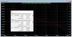
100p/390p with R increased from 1k to 2k produces 26db and 68 degrees with a 1MHz ULGF. Feedback bypass cap is 100R / 3.3p. This looks better to me.
Note: I had to change the values of the CCS resistors to get to the same currents that lineup has in his sims.
Note: I had to change the values of the CCS resistors to get to the same currents that lineup has in his sims.
Attachments
@brian92fs
I will try with your values, Brian. But to make it easier for builders I will use 2.2k ... not 2k
There is a voltage drop across base stoppers. In the CCS.
I will try with your values, Brian. But to make it easier for builders I will use 2.2k ... not 2k
There is a voltage drop across base stoppers. In the CCS.
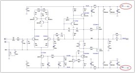
Lineup - So, tinkering some more, what do you think of this? To appeal to a wide variety of builders I think it would be good if the design worked with 20V to 56V rails. That would give you output options of 15W to 140W into 8R.
I attached my proposed changes with 20V and 56V rails to show that the design seems to support a wide range of rail voltages.
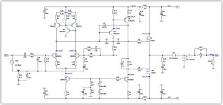
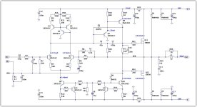
I updated the CCS of the design to use transistors instead of diodes which helps with slew rate. I also noticed that with higher rails, the negative slew rate was affected. Increasing the VAS current to 20ma fixed this. With these changes, I was able to use your earlier compensation. This seems to sim well for THD as well. The VAS and CCS transistors will run hot and definitely need heatsinks. But it seems doable.
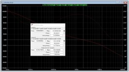
Stability shows 22db and 72 degrees with 56V rails.
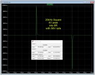
Slew rate looks good at +95/-113.
THD for 1K sims at 5 to 6 ppm across the output range. For 20k, it starts in the 20's ppm and runs up to 300+ ppm at clipping.
What do you think?
I attached my proposed changes with 20V and 56V rails to show that the design seems to support a wide range of rail voltages.
I updated the CCS of the design to use transistors instead of diodes which helps with slew rate. I also noticed that with higher rails, the negative slew rate was affected. Increasing the VAS current to 20ma fixed this. With these changes, I was able to use your earlier compensation. This seems to sim well for THD as well. The VAS and CCS transistors will run hot and definitely need heatsinks. But it seems doable.
Stability shows 22db and 72 degrees with 56V rails.
Slew rate looks good at +95/-113.
THD for 1K sims at 5 to 6 ppm across the output range. For 20k, it starts in the 20's ppm and runs up to 300+ ppm at clipping.
What do you think?
Attachments
I will post another thread: Cello Two
It will be for higher voltage supply.
I already made a simplified circuit for +/-30V. Will put out 38Watt rms.
With acceptable low distortion.
You are welcome to help me in that thread.
I will create that thread in a few days.
I see you use 10k+10k for CCS transistors.
Will feed less than 1 mA into the load
Self in Blameless uses approximate 2mA. (36V/20k = 1.8mA)
@brian92fs
I think those 2 MOSFETs can take a lot of power. They are robust.
So, one should be able to use rather high voltage supply.
Your schematic could be a start of that thread.
I think those 2 MOSFETs can take a lot of power. They are robust.
So, one should be able to use rather high voltage supply.
Your schematic could be a start of that thread.
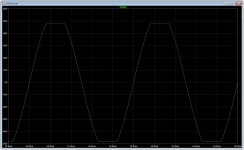
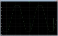
Put a base resistor on your Q10 and run the sim again.Here's clipping for 1k, 10k and 20k. Shows rail sticking at higher frequencies. Not sure how to address this.
Yes. Also of course change gain resistors.You're right. So those resistors would need to be modified for higher or lower rail voltages.
Looks like the spikes you have as the amp comes out of negative rail clipping are because the VAS current source is going OFF as the amp recovers. As soon as it recovers because the input signal has moved away from the peak, the current source is goes active again and you get the correct behavior. You have rail sticking on the negative swings because the current source is going into saturation. You might want to try a Baker clamp from the base to the collector of the current source transistor to address this.Here's clipping for 1k, 10k and 20k. Shows rail sticking at higher frequencies. Not sure how to address this.
Good to see the Baker clamp works around one single transistor.
The Baker diode should be not only low capacitance but also have sufficiently low enough Vf so it can clamp the transistor it's wrapped around, especially important for a single transistor, low Vf is less critical when wrapped around two transistors in a cascade as seen in the upper VAS section.
@brian92fs , remember, just because the Baker clamp saves the VAS transistor from sticking, it still causes the biasing voltage fed via resistor network (R14-R15 in your schematics #249) to both LTP CCS and VAS CCS to dip every time VAS output clips to negative, that's because either the VAS transistor via base-emitter diode and/or via Baker diode will hog all current during negative clipping.
In your earlier schematics in post #216 there was no capacitor (C9) next to the LTP CCS and that was also a concern for my post #217 because that could have taken down the LTP CCS current quite a bit and potentially causing a latch up when the LTP may not be able to make the upper VAS to pull back, but now that you have added a capacitor next to LTP CCS it helps to a degree filtering out those clipping dips, but it may still be modulating the LTP current a bit during clipping, maybe not so important though as long as it doesn't cause a problem, after all the music is awfully loud when nearing clipping.
Perhaps separate LTP and VAS CCS could be an idea.
Last edited:
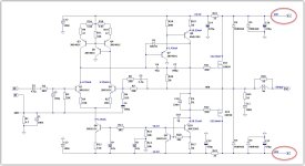
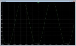
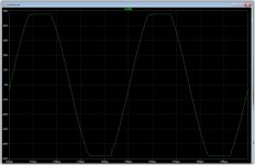
Seperate CCS's does seem to work better. Clipping response is good even without the Baker Clamp. Adding it cleans it up a bit further. And slew rate is better and symmetrical.
This is for 20V rails as lineup originally intended. The compensation was tweaked to account for the changes. It comes in at 18db and 65 degrees at a ULGF of 2MHz.
This is for 20V rails as lineup originally intended. The compensation was tweaked to account for the changes. It comes in at 18db and 65 degrees at a ULGF of 2MHz.
Attachments
- Home
- Amplifiers
- Solid State
- Cello One. Good Amplifier 15 Watt with TMC and Laterals