
Tokin à la Sit 4 ?
here also some inputs about JM. https://www.diyaudio.com/community/threads/jm-plantefeve-new-website-address.403381/
https://2adiy.ovh/
here also some inputs about JM. https://www.diyaudio.com/community/threads/jm-plantefeve-new-website-address.403381/
https://2adiy.ovh/
@grunf What JFET-s are you using in your final design? I noticed, that you also tried JFE2140. How would you compare it to with IF170?
I have experienced sound quality loss with chinese 23 Step Attenuator using Vishay Dale resistors. Do you have a better plan or option how to still have the Hi-Fidelity and to change the volume besides Alps RK27 pot?
Also looking for regulator schematics. 😉
I have experienced sound quality loss with chinese 23 Step Attenuator using Vishay Dale resistors. Do you have a better plan or option how to still have the Hi-Fidelity and to change the volume besides Alps RK27 pot?
Also looking for regulator schematics. 😉
I was wondering whether I could raise idle current of the output transistors to, say 0,7A, in order to get into Class A operation, lowering the PS voltage. I really like this design of using two 2SK170 JFETs (I happen to have plenty of them, all genuine purchased back in the late 1990s), instead of the complementary pair with 2SJ74 (of which I have not as much). But I always preferred playing in Class A and, as I understand, the Cube operates in Class AB. Of course, I haven't listened to it to judge - just saying...
You can essentially take any fully complementary circuit and replace the 2SJ74 with a 2SK170, wired as constant current source.
This is the case here, but you can see the same in Wayne's line stage at the Pass forum.
You loose half the open loop gain (input stage no longer push pull).
So if nothing changes, distortion goes up by 6dB, mostly H2.
If you want to use a pair of K170s for Class A power amp, you should look at the many Kaneda designs on the net.
At least that's what I would do.
https://www.diyaudio.com/community/threads/narsis-kaneda-mosfet-amp-built.416094/
https://solidstate.exblog.jp/1809626/
https://www.diyaudio.com/community/...-described-by-paul-kemble.220923/post-7797133
Patrick
IF170A is in my final design. The JFE2140 is not in the same Ids range so I didn't even consider it in this case. He is currently only on paper in the amplifier from post 17.@grunf What JFET-s are you using in your final design? I noticed, that you also tried JFE2140. How would you compare it to with IF170?
I have experienced sound quality loss with chinese 23 Step Attenuator using Vishay Dale resistors. Do you have a better plan or option how to still have the Hi-Fidelity and to change the volume besides Alps RK27 pot?
Also looking for regulator schematics. 😉
As for the pot, I think the Alps RK27 is quite a good choice. I have a P&G in Le Monstre, which in my opinion is the best I've tried, but the downside is that it's a slide pot and 120mm long because it's intended for studio mixers and consoles. I would certainly avoid those chinese steppers with questionable resistors.
Last edited:
It's not a problem to push it into A class, I have a quiescent current trimmer on my PCB and the power supply is dimensioned that way, but the current heatsink does not allow experiments with higher currents.I was wondering whether I could raise idle current of the output transistors to, say 0,7A, in order to get into Class A operation, lowering the PS voltage. I really like this design of using two 2SK170 JFETs (I happen to have plenty of them, all genuine purchased back in the late 1990s), instead of the complementary pair with 2SJ74 (of which I have not as much). But I always preferred playing in Class A and, as I understand, the Cube operates in Class AB. Of course, I haven't listened to it to judge - just saying...
This amplifier is a complete surprise to me, but only with the regulators, which is obvious because of the simple design. My Le Monstre hasn't been played for more than three months, and I have to admit that I pushed through the summer heat more easily.
Nothing, but then we leave the operating points that JM imagined. There would certainly be some changes in the sound, you should try it, but this amplifier sounds good enough that it should not be pushed into the A class.what prevents us ti bias the cube in class A?
Attachments

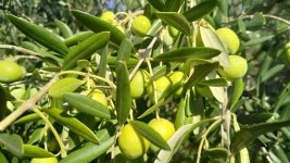
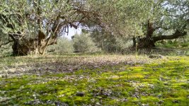
olives harvested, processing finished, we got 105 liters of extra virgin olive oil, an excellent result considering that the last 6 years were bad due to drought
I still have to paint the wooden boat and then I'm back to DIY
I still have to paint the wooden boat and then I'm back to DIY
Attachments
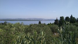
@Ejam, The city of Šibenik is in the background of the second photo and the island is Prvić, the village is Prvić Luka. 😉
Attachments

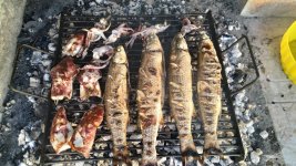
and some more good fried fish 🙂Excellent results indeed Grunf.
EVOO is all we use, I would like 2 liters please 😁.
The Adriatic squid in the picture is a top specialty, unfortunately it is slowly disappearing due to overfishing and climate change.
Attachments
Dear grunf,
A couple of questions regarding this project.
From post #21:
It's not a problem to push it into A class, I have a quiescent current trimmer on my PCB and the power supply is dimensioned that way, but the current heatsink does not allow experiments with higher currents.
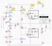
As I understand, you have followed ZoltanChivay's circuitry shown in post #8. This has 2 trimmers:
R16 - DC regulation at the output
R15 - bias
In your implementations, I notice that you use 3 trimpots. I assume that the third is used to set the quiescent current, as you say that you have added that option. Forgive my ignorance, but doesn't the bias setting regulates the quiescent current? I'm a little confused here. Could you please show a schematic of the circuit that you actually built? I'm considering building this amp and I too would like to experiment with higher quiescent currents.
Thank you,
Evangelos
A couple of questions regarding this project.
From post #21:
and in post #90:Adjusting the offset and quiescent current is not complicated and does not take long. Quiescent current is not adjusted in the original scheme, but I added that option mostly because I want to do some experiments with the replacement of transistors.
It's not a problem to push it into A class, I have a quiescent current trimmer on my PCB and the power supply is dimensioned that way, but the current heatsink does not allow experiments with higher currents.
As I understand, you have followed ZoltanChivay's circuitry shown in post #8. This has 2 trimmers:
R16 - DC regulation at the output
R15 - bias
In your implementations, I notice that you use 3 trimpots. I assume that the third is used to set the quiescent current, as you say that you have added that option. Forgive my ignorance, but doesn't the bias setting regulates the quiescent current? I'm a little confused here. Could you please show a schematic of the circuit that you actually built? I'm considering building this amp and I too would like to experiment with higher quiescent currents.
Thank you,
Evangelos
- Home
- Amplifiers
- Solid State
- 'ceci est un Cube' amplifier from JM Plantefeve