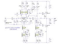
Has anyone built this amplifier? It looks simple but how does it sound? So far I've made a couple of similar amplifiers from JM Plantefeva with mixed results, so maybe I'll make this as well. It would be ideal as a summer amplifier because of the low idle current.
ceci est un Cube

ceci est un Cube
Attachments
Last edited by a moderator:
+1So far I've made a couple of similar amplifiers from JM Plantefeva with mixed results,
What I noticed is that most of its simplest schematic are very sensitive to the choice of components, the pairing of the input stage, the choice of the feedback level and that of the speakers. .
I played a lot with the Zenotron and the Amerotron a little over 20 years ago, I still have a Zenotron that I use from time to time with a pair of supravox 215 srtf and TQWT load, but I use really with pleasure that his N°217 NRDS and his Mosquito.
Today I really don't have much time to devote to all this but I will follow your thread with pleasure.
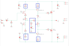
If I wanted to build it, I would first calculate how much the output offset voltage and the quiescent current can vary due to threshold voltage variations.
In fact I already did that for the output offset voltage, it could be up to +/- 3 V when J1 and J2 are at opposite sides of their tolerance intervals. You either have to use matched JFETs or to make R5 trimmable.
In fact I already did that for the output offset voltage, it could be up to +/- 3 V when J1 and J2 are at opposite sides of their tolerance intervals. You either have to use matched JFETs or to make R5 trimmable.
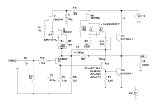
Instead of R4 and R5 are 100R + 100R trimmer.How did you adjust it? There is nothing to adjust in the schematic in post #1, but then again, it looks like a simulation schematic that might be incomplete.
Attachments
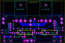
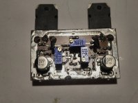
Is there a special reason why you changed the original scheme?here is the diagram I used to build the amplifier I added two potentiometers
R16 - DC regulation at the output
R15 - bias
finally some progress ") .
.
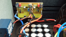
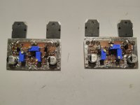
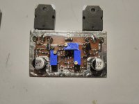
PCB made, all soldered. It remains to make the PCB for the rectifier and put everything together in the box. Instead of MJE243/253, ZTX851/951 are currently soldered. To begin with I will try them and I am also considering TTC011B/TTA006B from Toshiba( which are currently not available in Mouser). IF170A was used instead of LSK170A.
.PCB made, all soldered. It remains to make the PCB for the rectifier and put everything together in the box. Instead of MJE243/253, ZTX851/951 are currently soldered. To begin with I will try them and I am also considering TTC011B/TTA006B from Toshiba( which are currently not available in Mouser). IF170A was used instead of LSK170A.
Attachments
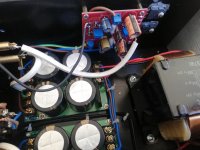
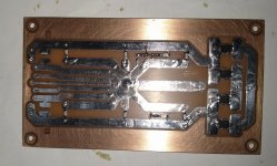
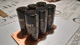
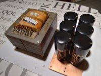
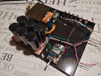
It took me a little longer to make this amplifier, today I finally finished the rectifier PCB, the 6pcs ALC10S 10000uF/80V are still missing.
Now I have a problem with the box because the one I thought was big enough is unfortunately not, I have to come up with something quickly.
Now I have a problem with the box because the one I thought was big enough is unfortunately not, I have to come up with something quickly.
Attachments
- Home
- Amplifiers
- Solid State
- 'ceci est un Cube' amplifier from JM Plantefeve