
Perhaps you are confusing me to kimmosto whos behind the VituixCAD?🙂 I just use it a lot and post a lot of experiments using it, there is tons of info on images, more than I'm able to put into words. Also a hobbyist and I find it difficult to express as writing what is quite easily seen in the simulations while adjusting parameters.I agree, and I think one of the challenges here, for me, is that I'm not professionally trained at this stuff. So I will sometimes use terminology that's inaccurate.
I think that Amir at AudioScienceReview and Erin at erinsaudiocorner have contributed a lot, and one of the most interesting contributions is seeing how enclosures impact frequency response and directivity.
Stereophile has published a lot of great information on speaker measurements, but their methods aren't particularly rigorous and their directivity measurements use a really bizarre format that went out of favor almost 30 years ago. I should buy Stereophile a Klippel lol.
I may be wrong, but the data that Erin and Amir have published, and the software that Mabat and you have published, seem to illustrate that it's possible to juggle these variables to extend directivity control an octave or two lower than you'd get with an infinite baffle: ...
It is great these tools exists, lots of data and real time or almost real time results allow all kinds of thought processes, generalizations, to be made. In addition we have increasing amount of Klippel results available, very interesting times for developing imagination and thought process for loudspeaker context. If not knowing how it all sounds in the end but at least there is more data for visual inspection, how the speaker structures work and how they affect measurements. While the simulation data is not necessarily exactly reality and imagination is not the same as numerical analysis still we have wavelength at the bottom of it, quite simple concept even though implications get complex fast.
... it's possible to juggle these variables to extend directivity control an octave or two lower than you'd get with an infinite baffle: ...
That seems to be about right, octave or bit more for extended pattern control with diffraction, but not sure if this is good or bad thing. Perhaps it is fine to use it for directivity control as most speakers happen to do, speakers that don't have extensive roundovers. It is really hard to get rid of it actually, extensive roundovers needed. Although I need to point out the difference is not that much on directivity in practical application even though it is visible on the graphs, signal is attenuated only few db to 90 deg, rarely on first reflection angle for example. It might make difference for perhaps more difficult crossovers (thinking passives) as the on-axis hump needs to be tamed and its usually at crossover frequency. Still it might be audible as it is delayed sound that makes the difference in frequency response plot but not sure if it is. If the frequency response is taken care in the filters, and diffraction is not let make more ripple than the main hump, perhaps its not audible and we can reap the extra directivity without downsides.
Last edited:
Earl Geddes and I were chatting back in the day, and he noted that something as simply as having a potted plant near the speaker impacted how it sounded.
That is exactly where the CBT has an advantage. Due to the differing position of each driver in the array, each with their specific position dependent reflections (that don't match the other driver's positions) they average out the environment much better, like the average of multiple microphone positions would clean up an IR.
A straight array does something similar, but still has the parallel planes and ridges (mostly) in common between drivers. Due to the bend nature, the CBT has an advantage there and thus,
it would measure(*) better in an untreated environment (or with a potted plant beside it). It does require proper placement to get that advantage (relative free position, not in a corner).
(*) aside from the warts due to the specific nature of it's build, e.g. due to driver size and center to center spacing etc.
Patrick,
See this arc-> https://www.fairaudio.de/test/audiophile-fast-cylindric-line-array-lautsprecher/
I got an idea. Make an arc like this and make the array slightly smaller ie make the array free standing CBT and aim it slightly upwards to ear height. Put a waveguided tweeter in the center. It would be really interesting if you could make the tilt passively like Wesayso did. This array for most of its bandwidth does not use the floor bounce.
I would suggest to try your idea in a simulation tool like Vituixcad first, as I don't see, after the several attempts I did, that the CBT is working as advertised in it's flyers.
In other words: I don't think we have seen much beyond some kind of ideal using very small sources. It would be rather difficult to repeat it with true life size drivers.
On top of that, the shading used throws away a lot of potential dynamics... I'd put my money on the Synergy.
I spent the better part of my three day holiday doing exactly that, and it is TRULY frustrating. The predicted performance of a CBT in VituixCad is almost shockingly bad. The only thing that really seemed to smooth things out was simulating at a very far distance.
Another thing I noticed was that the simulated performance was much improved if the "virtual microphone" is located at the center of the vertical array, and if the shading is done in such a way that the center of the array is the loudest.
The CBT papers seem to have some holes in them, IMHO:
1) They assume that the floor is a perfect mirror. (The loudest element in a CBT array, as sold by Parts Express, is on the floor.) But in the real world, we have furniture, and I don't have the luxury of placing the loudest element on the floor.
2) The CBT papers show pretty simulations that seem to be based on an element size that's impossibly small.
3) Unless I'm missing it somewhere, it's extremely difficult to find real world measurements of an actual CBT. There's some data in JBL's spec sheet, but it's limited. There's a DIY'er who published polars of his CBT about seven years back. And Amir measured a JBL CBT at audiosciencereview. All of this data is a bit tricky because all three CBTs vary significantly than what's in the CBT papers, in particular the JBL CBTs have a curvature that's dramatically smaller than the CBTs in the AES papers.
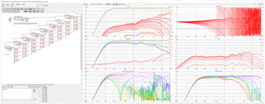
I was simulating CBTs about 3 years ago. I managed to get some Vituix modeling done that seemed reasonable but I too wasn't impressed with the results. Here is a screenshot from a sim of a full curve CBT, which didn't depend on ground reflection, if you would like to compare results. Above 1 Khz, the vertical directivity falls apart. These things really depend on having a tiny tweeter next to small mids. If you aren't willing to do that, you are better off with a non-CBT full range driver line array.
Attachments
It's not in the manual, but ATH can simulate CBT arrays, and create the config files required to simulate them in ABEC.
Attached is the following:

Here's the config file that you can use to generate the forty degree curved CBT array that's pictured in the attached sims.
; cbt.txt - source array demo
; --------------------------------------------------------
; use with ath-beta-221115:
; https://www.at-horns.eu/release/ath-beta-221115.zip
HornGeometry = 2
Length = 1
Throat.Diameter = 53
Throat.Angle = 0
Horn.Adapter = { ; rectangular throat area
Width = 88.9 ; [mm]
Height = 1400 ; [mm]
Segments = 0 ; must be 0
}
Source.Array = {
Elem.Shape = 0 ; element shape: 0 = circular; 1 = rectangular
Elem.Diameter = 44 ; [mm]
Elem.Spacing = 23 ; space between elements [mm]
Elem.Group = 1 ; number of elements per group
; Split = 0
Arc.Angle = 20 ; bend angle [deg]
Shading = 1 ; 1 = CBT/Keele level
}
Horn.Part:1 = {
L = 1
Segments = 0
H = {
k = 0
s = 1
q = 0.995
n = 2.0
r0 = 53
a0 = 0
a = 80
}
V = {
k = 0
s = 1
q = 0.995
n = 2.0
r0 = 53
a0 = 0
a = 80
}
ZMap = 0.5,0.3,0.5,0.9
}
; -------------------------------------------------------
Mesh.AngularSegments = 64
Mesh.ThroatResolution = 6
Mesh.MouthResolution = 10
Mesh.RearResolution = 25
Mesh.SubdomainSlices =
Mesh.InterfaceOffset = 0
Mesh.InterfaceResolution = 6
Mesh.WallThickness = 100
Mesh.ZMapElementSize = 0.3,0.6,0.5,0.95
; -------------------------------------------------------
ABEC.SimType = 2
ABEC.f1 = 250 ; [Hz]
ABEC.f2 = 8000 ; [Hz]
ABEC.NumFrequencies = 61
ABEC.MeshFrequency = 1000 ; [Hz]
; -------------------------------------------------------
ABEC.Polars:SPL_H = {
MapAngleRange = 0,180,37
Distance = 3
;NormAngle = 0
}
ABEC.Polars:SPL_V = {
MapAngleRange = 0,90,19
Distance = 3
;NormAngle = 0
Inclination = 270
}
; -------------------------------------------------------
Output.STL = 1
Output.ABECProject = 1
Report = {
PolarData = "SPL_H"
Title = "Dayton Epique CBT - Horizontal"
Width = 2880
Height = 1620
;MaxAngle = 0
NormAngle = 10
}
Attached is the following:
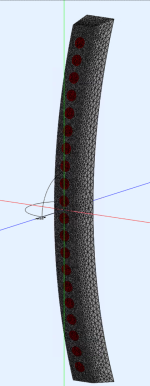
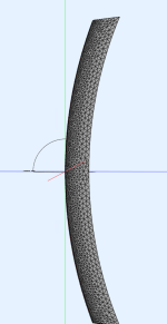
- pics of what the CBT array looks like.
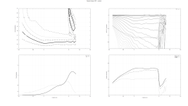
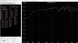
- sims of the normalized vertical response measured on-axis.
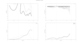
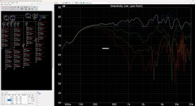
- sims of the normalized vertical response measured 20 degrees off-axis.
- sims of the normalized horizontal response measured 10 degrees off-axis.
- All of the Keele papers assume that the floor acts like a perfect mirror. It might not be immediately obvious, but the shading used in a CBT means that the listening axis of the speaker is on the floor. If you look at these sims that show an arc, only the top half is typically built. The idea here, is that you can control directivity down to one octave lower, if you use the floor as a mirror. But I've seen a lot of people who've built CBTs, who then measure the speaker like they would measure a "normal" speaker. IE, they raise it off the ground. This isn't "correct." Realistically, CBTs should probably be measured with the microphone on the ground. (Which work surprisingly well, if the speaker is designed like that.) I haven't simmed what happens when you take a CBT and put it a foot or a meter in the air, but I imagine it will lead to some floor bounce polluting the measurement, and it will also make the vertical polar response asymmetrical. Basically, if you're using the published CBT shading, the speaker should probably be on the floor. Even putting it on top of a sub or a stand will impact performance.
- The response SHAPE of a CBT is insanely consistent, especially when you're nearly on-axis. Due to this, the SHAPE of the response shouldn't vary much if your head is on the floor, your head is at seated level, or you are standing. BUT, the LEVEL will vary. Odd as this sounds, a CBT is loudest at the floor and gets gradually quieter (while maintaining response shape) as you get higher and higher. (Basically as you move ABOVE the loudest axis, which is on the floor.)
- If you put all of that together, you can see that one could make a free standing CBT that's a full convex arc, and put the listening axis in the MIDDLE. But if you did that, directivity control would collapse one octave higher in frequency, than if the CBT was on the floor, and shaded to be there.
- You can see that directivity and frequency response go FUBAR as soon as the frequencies are smaller than the diaphragm of the radiator. I did these sims with a Dayton ND64-16 (same driver that Keele used in the Epique CBT) and you can see the response falls apart at 7727Hz. Not coincidentally, the diameter of the diaphragm is 44mm, which is 7727Hz long. If I'm not mistaken, if you could find a diaphragm that produced a perfectly flat wavefront, these response issues wouldn't be a problem. If you look at some of Folgott's CBT projects on here, he used "vanes" to keep the CBT drivers from interfering with each other: https://www.diyaudio.com/community/...totype-with-waveguide-and-cbt-shading.266417/
Here's the config file that you can use to generate the forty degree curved CBT array that's pictured in the attached sims.
; cbt.txt - source array demo
; --------------------------------------------------------
; use with ath-beta-221115:
; https://www.at-horns.eu/release/ath-beta-221115.zip
HornGeometry = 2
Length = 1
Throat.Diameter = 53
Throat.Angle = 0
Horn.Adapter = { ; rectangular throat area
Width = 88.9 ; [mm]
Height = 1400 ; [mm]
Segments = 0 ; must be 0
}
Source.Array = {
Elem.Shape = 0 ; element shape: 0 = circular; 1 = rectangular
Elem.Diameter = 44 ; [mm]
Elem.Spacing = 23 ; space between elements [mm]
Elem.Group = 1 ; number of elements per group
; Split = 0
Arc.Angle = 20 ; bend angle [deg]
Shading = 1 ; 1 = CBT/Keele level
}
Horn.Part:1 = {
L = 1
Segments = 0
H = {
k = 0
s = 1
q = 0.995
n = 2.0
r0 = 53
a0 = 0
a = 80
}
V = {
k = 0
s = 1
q = 0.995
n = 2.0
r0 = 53
a0 = 0
a = 80
}
ZMap = 0.5,0.3,0.5,0.9
}
; -------------------------------------------------------
Mesh.AngularSegments = 64
Mesh.ThroatResolution = 6
Mesh.MouthResolution = 10
Mesh.RearResolution = 25
Mesh.SubdomainSlices =
Mesh.InterfaceOffset = 0
Mesh.InterfaceResolution = 6
Mesh.WallThickness = 100
Mesh.ZMapElementSize = 0.3,0.6,0.5,0.95
; -------------------------------------------------------
ABEC.SimType = 2
ABEC.f1 = 250 ; [Hz]
ABEC.f2 = 8000 ; [Hz]
ABEC.NumFrequencies = 61
ABEC.MeshFrequency = 1000 ; [Hz]
; -------------------------------------------------------
ABEC.Polars:SPL_H = {
MapAngleRange = 0,180,37
Distance = 3
;NormAngle = 0
}
ABEC.Polars:SPL_V = {
MapAngleRange = 0,90,19
Distance = 3
;NormAngle = 0
Inclination = 270
}
; -------------------------------------------------------
Output.STL = 1
Output.ABECProject = 1
Report = {
PolarData = "SPL_H"
Title = "Dayton Epique CBT - Horizontal"
Width = 2880
Height = 1620
;MaxAngle = 0
NormAngle = 10
}
Attachments
-
 041225-cbt20-vertical0.png316.7 KB · Views: 55
 -
 041225-cbt20-vertical20.png328.8 KB · Views: 46
 -
 041225-cbt20-horizontal10.png226.5 KB · Views: 41
 -
 Screenshot 2025-04-12 112059.png432.9 KB · Views: 41
 -
 Screenshot 2025-04-12 112139.png280 KB · Views: 45
 -
 Screenshot 2025-04-12 112210.png491.7 KB · Views: 44
The obvious solution to the lack of highs in a CBT array is to put a tweeters in the middle of the array.
I don't think this works; I have generally found that if you put a 'hole' in the center of a CBT array, by replacing one of the mids with a tweeter, the response falls apart.
I believe that this is largely because the center driver in a CBT array is the loudest; when you remove it, the performance collapses.
Due to that, it seems like the only good location for a tweeter in a CBT array is:
1) a full height line of tweeters, with CBT shading, similar to the JBL and Parts Express CBT arrays
2) Or a tweeter that's close enough to the CBT array that it will behave as if it's a single unit.
That last one is a bit of mystery to me TBH; for instance, I need to explore whether it's possible to have a full range driver or a Unity horn in the center of the array, while the rest of the array "only" plays to about 5khz.
I've attached four pics:
- The first pic shows the horizontal response of a two-way loudspeaker. The low frequencies are radiated by a sixteen element CBT array using the Dayton ND64-16. This is the same driver that Don Keele created for the Dayton "CBT Epique" speaker. The Keele speaker used 24 drivers. My sim uses 32 drivers, because the floor is intended to act as an "acoustic mirror." (Check the Keele PDF docs for more info on that.) The high frequencies are provided by a Fountek ribbon, which is now sold by GRS at PE.
- The second pic shows the vertical response of a two-way loudspeaker. The low frequencies are radiated by a sixteen element CBT array using the Dayton ND64-16. This is the same driver that Don Keele created for the Dayton "CBT Epique" speaker. The Keele speaker used 24 drivers. My sim uses 32 drivers, because the floor is intended to act as an "acoustic mirror." (Check the Keele PDF docs for more info on that.) The high frequencies are provided by a Fountek ribbon, which is now sold by GRS at PE.
Attachments
- Home
- Loudspeakers
- Multi-Way
- CBT wrapped around a Unity Horn