The fundamental issue with CBT arrays, and arrays in general, is that the high frequencies aren't well behaved. In the attached measurement of the Parts Express CBT24, you can things work great... up until about 2500Hz.
A thought I had, is that you might be able to wrap a CBT array around a Unity Horn. The Unity horn would have to be very very small; basically small enough to blend with the CBT array.
But this might be a way to get "the best of both worlds:"
1) Based on years of experimentation, I've found that speakers with wide horizontal directivity and narrow vertical directivity are ideal
2) But if you want to achieve that goal with a conventional Unity Horn, you end up with a mouth that's about the size of a door, like a Danley Jericho
Attachments

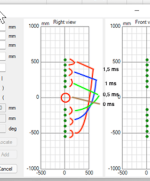
Here's how the vertical polars look for a full-range vertical array that's flat.
Basically no enhancements to improve the bandwidith or beamwidth. Just a plain ol' flat vertical array.
There's a hole in the middle of the array - that's there for the Unity Horn that I'll add later.
But the main point - you can use this array up to about 500Hz, give or take half an octave.
Basically no enhancements to improve the bandwidith or beamwidth. Just a plain ol' flat vertical array.
There's a hole in the middle of the array - that's there for the Unity Horn that I'll add later.
But the main point - you can use this array up to about 500Hz, give or take half an octave.
Attachments

This is hardly authoritative, but I made some ZMA and FRD files for the Dayton ND64-16 that's used in the Dayton Epique CBT24 that's no longer for sale. (You can't buy the speakers but you can buy the drivers.) They're basically expressly designed for arrays, with a rising high frequency response.
Attachments
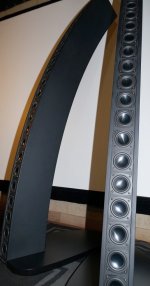
I was tinkering with the way that JBL "curves" their CBTs, in speakers like the JBL CBT 100. The speaker is physically flat, but theoretically the wavefront is curved (like a CBT is supposed to be.)
When tinkering around with it, I realized the so-called "CBT 100" really isn't a CBT: the wavefront is just barely curved, and it's ONLY curved at very high frequencies.
This is because the delay is accomplished via passive crossover delay.
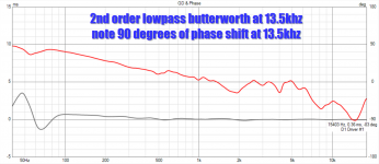
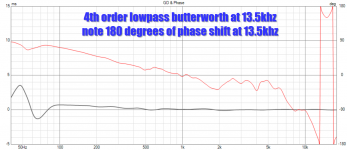
Another thing that I found interesting, was that the delay wasn't as much as I'd expected. For instance, as I understand it, a 4th order xover has 360 degrees of delay at the xover point. In other words, if you set a 4th order low pass xover at 13,500Hz, I thought the delay would be 2.54cm. (13500Hz is 2.54cm long, or one inch.)
I may need to go buy a crossover textbook lol
Another possibility here, is that the delay is the combination of both the high pass and low pass. IE, you may get 360 degrees of delay from a combination of both the low pass and the high pass at the xover point?
The bottom line here: It looks like I'll probably need to PHYSICALLY curve the array. I was hoping it might be possible to do it via the xover, but that doesn't appear to be the case. Obviously, I could curve it with DSP delay, but there's no way I'm going to go buy 24 channels of amplification lol.
BTW, a lot of these discoveries were already made by yours truly here: https://www.diyaudio.com/community/...rray-its-a-modified-cbt24.313352/post-5517041
I have a habit of pondering designs, get frustrated with them, then pick them back up a few days/months/years later.
When tinkering around with it, I realized the so-called "CBT 100" really isn't a CBT: the wavefront is just barely curved, and it's ONLY curved at very high frequencies.
This is because the delay is accomplished via passive crossover delay.
Another thing that I found interesting, was that the delay wasn't as much as I'd expected. For instance, as I understand it, a 4th order xover has 360 degrees of delay at the xover point. In other words, if you set a 4th order low pass xover at 13,500Hz, I thought the delay would be 2.54cm. (13500Hz is 2.54cm long, or one inch.)
I may need to go buy a crossover textbook lol
Another possibility here, is that the delay is the combination of both the high pass and low pass. IE, you may get 360 degrees of delay from a combination of both the low pass and the high pass at the xover point?
The bottom line here: It looks like I'll probably need to PHYSICALLY curve the array. I was hoping it might be possible to do it via the xover, but that doesn't appear to be the case. Obviously, I could curve it with DSP delay, but there's no way I'm going to go buy 24 channels of amplification lol.
BTW, a lot of these discoveries were already made by yours truly here: https://www.diyaudio.com/community/...rray-its-a-modified-cbt24.313352/post-5517041
I have a habit of pondering designs, get frustrated with them, then pick them back up a few days/months/years later.
Attachments
So you have 12 LF drivers per side. If you section these into pairs (and a mirror pair below centre), there is a need for 3 channels per stereo side. An eight channel DAC would be able to feed 3 channels of delayed pairs per stereo side and 1 HF channel per side. Now you can delay so to get a spherical wavefront of the line? (I just winged the delays...)
I have been thinking of building such a thing myself but with 8 driver pairs per side (tot of 16 LF drivers - (ceiling_to_roof_in_corner)+ HF/side) and each driver pair with its own DAC and amp feed by CamillaDSP.
//
I have been thinking of building such a thing myself but with 8 driver pairs per side (tot of 16 LF drivers - (ceiling_to_roof_in_corner)+ HF/side) and each driver pair with its own DAC and amp feed by CamillaDSP.
//
Attachments
Last edited:
Patrick,
If you go active analogue then delay is possible by cascaded all-pass-filters avoiding the need of physical curvature. See Figure 31 in https://www.ti.com/lit/ug/tidu035/tidu035.pdf. A few op-amps can do it. I am surprised that this technique is not well known.
If you go active analogue then delay is possible by cascaded all-pass-filters avoiding the need of physical curvature. See Figure 31 in https://www.ti.com/lit/ug/tidu035/tidu035.pdf. A few op-amps can do it. I am surprised that this technique is not well known.
nc535 worked a lot with integrating a line of LF with a single source HF - check #734 at https://www.diyaudio.com/community/...-corner-placement.337956/page-37#post-6485604
//
//
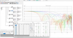
24x TC9 straight line array with frequency dependent filtering:

Quite a nice and even vertical beam, it only needs a ribbon or a horn in the center to complete it...
Loosely based on my own frequency shaded arrays... Part of that big thread of nc535...
No need for digital delay or CBT arc shapes etc, just passive filtering...
Add your own top end and subwoofer, done... 😀
wesayso,
Thats quit a nice polar plot.
What are the rules for CRL of each block of drivers? I expected to see a pattern but it doesnt seem to follow any. And why the extra C12?
Thats quit a nice polar plot.
What are the rules for CRL of each block of drivers? I expected to see a pattern but it doesnt seem to follow any. And why the extra C12?
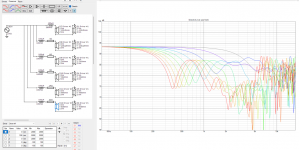
I've created that graph quite a while ago by concentrating on the vertical beam-width. To get that beam as even as possible by manually tweaking the values.
That extra C12 is creating top end roll off of the central group surrounding the (yet to be implemented) tweeter.
It was kind of a proof of concept to show what could be done if one started from scratch, as it was loosely based on my filtered arrays that have a similar vertical
beam, but still a full range driver group top end:
.png")
Compared to my arrays when they were unfiltered:

Differences in reduced combing are pretty obvious, but also the vertical beam forming properties. The lobes up top are due to
the center to center spacing of the drivers.
That extra C12 is creating top end roll off of the central group surrounding the (yet to be implemented) tweeter.
It was kind of a proof of concept to show what could be done if one started from scratch, as it was loosely based on my filtered arrays that have a similar vertical
beam, but still a full range driver group top end:
Compared to my arrays when they were unfiltered:
Differences in reduced combing are pretty obvious, but also the vertical beam forming properties. The lobes up top are due to
the center to center spacing of the drivers.
After doing some fairly intricate messing around with curved CBTs, I find it difficult to understand how Keele produced these pretty graphs in his documentation. It just doesn't seem to compute. I can definitely achieve nice response in a window of about 20-30 degrees. But after that, there's some off-axis nulls that are quite brutal.
"Wesayso's" results in post nine look much nicer, but when you're "shading" the FREQUENCY response of the array, that's just another way of saying that you're doing a multi-element array. And if you're going to do a multi-element array, something like this makes more sense IMHO:
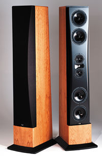
In a nutshell, if you're going to do a three way, or four way, or five way, you might as well use larger drivers for the low frequency units.
Of course, one reason to simply use all the same driver, as wesayso did, is cosmetics.
I guess I'm just a little frustrated that the results promoted in the Keele docs seem to be disconnected from what can be done in the real world. I wonder if his sims depended on a very very small driver. Obviously, if the center-to-center spacing is reduced to an inch or half an inch, things will start to look a lot better.
"Wesayso's" results in post nine look much nicer, but when you're "shading" the FREQUENCY response of the array, that's just another way of saying that you're doing a multi-element array. And if you're going to do a multi-element array, something like this makes more sense IMHO:
In a nutshell, if you're going to do a three way, or four way, or five way, you might as well use larger drivers for the low frequency units.
Of course, one reason to simply use all the same driver, as wesayso did, is cosmetics.
I guess I'm just a little frustrated that the results promoted in the Keele docs seem to be disconnected from what can be done in the real world. I wonder if his sims depended on a very very small driver. Obviously, if the center-to-center spacing is reduced to an inch or half an inch, things will start to look a lot better.
One more thing -
In a lot of ways I'm accidentally re-tracing the steps of Follgott. He tried CBTs and ended up building something similar to the Snell eXpanding Arrays, but with Fir filters.
In a lot of ways I'm accidentally re-tracing the steps of Follgott. He tried CBTs and ended up building something similar to the Snell eXpanding Arrays, but with Fir filters.
I have tried to run a few CBT sims too, I never succeeded to get better looking results than my straight frequency filtered arrays.
So with real world drivers I think it's not as pretty as the documents said it was...
I get your point about having bigger drivers for the bottom end, but it isn't that easy to get the beam shape as nice without the output in the middle.
Dunlavy was no fool though and most certainly an inspiration for my array project.
It certainly works well enough for me and made me consider stepping it up a notch...

(because after being about 10 years of age and stored in a damp place for a year I lost some TC9's to corrosion/open circuit)
For a cool multi way project I'd refer to https://www.diyaudio.com/community/...raight-cbt-with-passive-xos-and-no-eq.330031/
as that is a multiple driver array that does seem to do a lot of things right. A smart choice of array placement with a good outcome. Not sure about it's
horizontal coverage though...
So with real world drivers I think it's not as pretty as the documents said it was...
I get your point about having bigger drivers for the bottom end, but it isn't that easy to get the beam shape as nice without the output in the middle.
Dunlavy was no fool though and most certainly an inspiration for my array project.
It certainly works well enough for me and made me consider stepping it up a notch...
(because after being about 10 years of age and stored in a damp place for a year I lost some TC9's to corrosion/open circuit)
For a cool multi way project I'd refer to https://www.diyaudio.com/community/...raight-cbt-with-passive-xos-and-no-eq.330031/
as that is a multiple driver array that does seem to do a lot of things right. A smart choice of array placement with a good outcome. Not sure about it's
horizontal coverage though...
I thought I read somewhere that a line array drops spl per metre differently than 'normal' speakers ? (-3dB per doubling of distance rather than -6dB per doubling of distance) Would that not be an issue if crossing between styles ? (Been a long day at work, just got in so haven't double checked and am relying on memory 😀)
edit, maybe only if its a floor to ceiling array ?
Rob.
edit, maybe only if its a floor to ceiling array ?
Rob.
As I understand it:
1) a point source gets 6dB quieter as the distance doubles
2) a perfect line source IN ONE AXIS gets 3dB quieter as the distance doubles
3) if you could make a speaker that's basically a laser beam, it wouldn't attenuate at all.
In the prosound world, they call these "long throw" and "short throw" speakers.
I've heard a few CBTs and one of the weird things about them is that they don't really get any louder as you get closer to them. Unity horns do something similar; you can put your head inside the horn and it doesn't seem a whole lot louder than if you were three feet away. It's bizarre.
Some delay of the outer groups is there from applying the passive filters, but no, not in that sense, it still is a somewhat bent line.
But in my defense, I wasn't trying to build a CBT, I have no intention to do so either. But maybe that question wasn't directed at me?
But in my defense, I wasn't trying to build a CBT, I have no intention to do so either. But maybe that question wasn't directed at me?
What I got out of the original post was the wish for narrow vertical directivity and hopefully small size. CBT being optional to achieve that.
I just posted what I considered some inspiration to achieve one of those goals.
I just posted what I considered some inspiration to achieve one of those goals.
- Home
- Loudspeakers
- Multi-Way
- CBT wrapped around a Unity Horn