I love the cascaded LTP as well
As this is my first post here a very short introduction: My name is Anton, living in Switzerland with a background in natural sciences and working in IT. In the late 1980s, early 1990s I built a number of tube amplifiers in the end settling on a cascode long tail pair driving KT88s or 6550 in PP.
I picked that hobby up again in the last few years and still staying with cascode LTPs for anything which needs a sizeable voltage swing to drive the power tubes. I am planning to create a little website around tube amps, but didn’t get around to do it yet, so I thought I might share it here.
So here are a few remarks concerning the key points from my perspective (and which in part were already mentioned in the thread). My assumption is 4V PP input at max drive and at least 80V PP output drive at full input level.
An optimized example: E88CC as the lower tube and ECC99 as the upper tube, 50k anode resistor and 66k upper tube bypass resistor. The lower tube’s anode at 110 V and the total voltage at 590V results in 300V peak peak at 4V pp input signal with -40dB third harmonics and no measurable (with my crude equipment) second harmonics. At that input level (soft) clipping starts to kick in. The whole loaded with a 100k grid bias resistor on each leg for the end tubes. For lower input drive voltages the distortion becomes negligible (still considering that I have a relatively crude measuring setup).
This gives plenty of wiggle room to drive KT88s, But is falls a little short for driving high power triodes if there should still be some global negative feedback possible. So what’s still open is:
As this is my first post here a very short introduction: My name is Anton, living in Switzerland with a background in natural sciences and working in IT. In the late 1980s, early 1990s I built a number of tube amplifiers in the end settling on a cascode long tail pair driving KT88s or 6550 in PP.
I picked that hobby up again in the last few years and still staying with cascode LTPs for anything which needs a sizeable voltage swing to drive the power tubes. I am planning to create a little website around tube amps, but didn’t get around to do it yet, so I thought I might share it here.
So here are a few remarks concerning the key points from my perspective (and which in part were already mentioned in the thread). My assumption is 4V PP input at max drive and at least 80V PP output drive at full input level.
- Use a constant current source on the cathodes of the LTP. This gives you better PSRR and CMRR than just a resistor.
- Use the same effective value for the grid return resistors on the lower tubes otherwise you risk to have a DC imbalance and thus different working points on the left and right leg of the LTP if the difference is large. The reason for this being the negative grid current which is brought to ground by the grid return resistors. The consequence of this is that part of the negative feedback loop needs to be capacitor coupled as the gain determining resistor going from the right tube grid to ground is usually max a few kilo Ohms whereas the grid return resistors are much larger. Alternatively the grid return resistors can just be made small as we usually will have enough drive power from the typical input sources.
- Use unbypassed cathode resistors on the lower tube in order to provide local feedback. This measurably linearises the response without overall negative feedback. They may also be used to adjust the amount of overall negative feedback allowed/needed.
- The lower tube of the cascode needs to have a large range of linear transconductance (and preferably a large transconductance) and the working point must be in the middle of the linear range. So e.g. an E88CC needs to be run at 10-12.5 mA per triode at around 100V at the anode.
- The lower tube needs to have a large transconductance. If we make a first oder assumption of the gain as being lower tube transconductance times the load resistance a large transconductance gives us a higher gain and allows us to choose a smaller anode resistor for the upper tube thus increasing driving capability without using a separate driver stage.
- Have a high voltage available to the upper tube to allow the upper tubes to operate in a linear range with a large voltage swing.
- The consequence of this is that the upper tube needs to be able to handle quite a bit of power.
- It may be necessary to bypass the upper tube with a resistor to get the optimal working points of lower and upper tube
An optimized example: E88CC as the lower tube and ECC99 as the upper tube, 50k anode resistor and 66k upper tube bypass resistor. The lower tube’s anode at 110 V and the total voltage at 590V results in 300V peak peak at 4V pp input signal with -40dB third harmonics and no measurable (with my crude equipment) second harmonics. At that input level (soft) clipping starts to kick in. The whole loaded with a 100k grid bias resistor on each leg for the end tubes. For lower input drive voltages the distortion becomes negligible (still considering that I have a relatively crude measuring setup).
This gives plenty of wiggle room to drive KT88s, But is falls a little short for driving high power triodes if there should still be some global negative feedback possible. So what’s still open is:
- A test with a much higher voltage (around 1000V) across the upper tubes to avoid the bypass resistors. It is not easy to find a standard (not high power) triode with the corresponding voltage rating though.
- And a test with a very high transconductance lower tube (6C45Pi) and a high overall voltage as well. There again a bypass resistor will be needed as the linear range will likely be at higher anode currents than for the E88CC.
Attachments
Hi Toniburner,
Take note of the H(eater)-K(athode) ratings of your tubes. I think its only 200 Volt for the ECC99, so make sure how to heat the tubes with respect to the kathode voltage.
Please keep us updated with your findings.
Regards, Gerrit
Take note of the H(eater)-K(athode) ratings of your tubes. I think its only 200 Volt for the ECC99, so make sure how to heat the tubes with respect to the kathode voltage.
Please keep us updated with your findings.
Regards, Gerrit
Alright, so I built a prototype, and want to approach this in stages, so I started with the LTP without the cascodes first but I am a little puzzled by what I'm seeing on the bench so was hoping someone else could offer some insights?
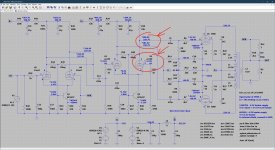
Please refer to the attached schematic, this is what I have running on the bench, the DC operating voltages noted with a * are measured values, the ones below what the simulator predicts. Take note that I adjusted the KT88s to pass the same mount of bias current, so the negative bias voltage on their grids differs.
The thing that I find puzzling though is that the grids of the ECC99 sit at a positive and negative (!) voltage? That can't be right. I swapped the ECC99 already for a new one, also tried a few 6922 as they pretty much run at the same bias point, but this difference stays. Obviously I checked the wiring, actual parts values, replaced the coupling caps etc. many times but I can't seem to find a fault anywhere?
Attachments
Take note of the H(eater)-K(athode) ratings of your tubes. I think its only 200 Volt for the ECC99, so make sure how to heat the tubes with respect to the kathode voltage.
Yes that is something which one has always to take care of in this kind of circuit. But as I am running the lower tubes at around 100V anode voltage this is still in safe territory. Btw. using an E88CC for the upper tubes also works very well and even there with most makes of them the heater - cathode voltage is ok. I.e. heater grounded. The ECC99 can take more anode dissipation though.
Anton
Hi,
assuming this is not a measuring artefact, the only way I can imagine a negative voltage at U4's grid is that your grid return resistor R21 is either open or has a much higher value than anticipated as you charge the grid with electrons impinging on it and have no good path to ground to get rid of them. If R21 is in fact open and you apparently get some current through U4 there is a leak resistance to ground e.g. through the wood of the breadboard.
I suggest measuring the resistance from each of the grids U3 and U4 to ground.
Anton
Yes very good point try lifting the high impedance grid bits off the wood. You could be getting some current off the negative bias on one side. Interesting! I've used upside down cut up bits of stripboard before and super glue onto your wood.
Post #81. Interesting you have R10 and C5. This causes the NFB to increase (lead) at very low frequencies. This help considerably with LF stability when you have coupling caps and the OPT.
Hi,
assuming this is not a measuring artefact, the only way I can imagine a negative voltage at U4's grid is that your grid return resistor R21 is either open or has a much higher value than anticipated as you charge the grid with electrons impinging on it and have no good path to ground to get rid of them. If R21 is in fact open and you apparently get some current through U4 there is a leak resistance to ground e.g. through the wood of the breadboard.
I suggest measuring the resistance from each of the grids U3 and U4 to ground.
Anton
I’ve measured everything front to back several times, the wood isn’t the issue either, measuring two nails 5mm apart gives >100 mega Ohm. I’m leaning more towards an oscillation and will check for that when I get back into the office.
Circuit in #83
Which part of that is the Cascode connexion? Looks all Cascade to me. The grid in question is still negative in respect to its cathode the way it needs to be. But why the stage is unbalanced is a mystery. Leaky grid capacitor C14 perhaps? But that would create an imbalance at the previous driving plate.
Need to look with a wideband scope & a search probe for RF. I found oscillation at +100 MHz when an FM receiver I was listening to nearby was acting strangely while the circuit in test was running.😱
Have you tried a different U3/U4?
Last edited:
Just as a different comment I would think that current mirrors would work better for Q1 and Q2 say with a 1 to 50 current ratio using say .6 across the VBE and .4 across the emitter resistors. This would allow lower cathode voltages. It removes some of the temperature depencence. I don't think its oscillation but if you probe Q2 collector with say a bit of wire and the voltage on the ECC99 plates changed that would prove it. It could also be Q2 oscillation but again not likely.
Attachments
Last edited:
I think 5mA per tube is a bit low for a 6N6P, people tend to run those around 10~15mA/tube to get low distortion.Just as a different comment I would think that current mirrors would work better for Q1 and Q2 say with a 1 to 50 current ratio using say .6 across the VBE and .4 across the emitter resistors. This would allow lower cathode voltages. It removes some of the temperature depencence. I don't think its oscillation but if you probe Q2 collector with say a bit of wire and the voltage on the ECC99 plates changed that would prove it. It could also be Q2 oscillation but again not likely.
I’ve measured everything front to back several times, the wood isn’t the issue either, measuring two nails 5mm apart gives >100 mega Ohm. I’m leaning more towards an oscillation and will check for that when I get back into the office.
Probably needless and maybe even insulting to ask if you measured it also with the first LTP tube and endtubes removed and endtube grid bias switched off.
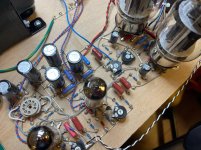
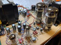
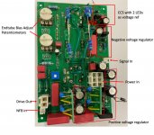
Here is my setup (just to prove I am not an armchair theoretican) - it is a sort of universal driver PCB with positive voltage regulator, negative voltage regulator (for the cascode not the bias), CCS and bias potentiometers for the end tubes included.
For measurements/tests I just solder some improvised stuff on it as you can see.
Heater wiring can be adjusted via bridges (not used in the image) and there are also different options for putting the anode and bypass resistors on it.
The size is 160mmx100mm.
For measurements/tests I just solder some improvised stuff on it as you can see.
Heater wiring can be adjusted via bridges (not used in the image) and there are also different options for putting the anode and bypass resistors on it.
The size is 160mmx100mm.
Attachments

.png") Just going with what Mr. SS is using and the plate resistors. I would probably use E88CC rather than ECC99 if the plate dissipation is OK and the supply voltage. Nearly pin compatible too with exception of heaters.
Just going with what Mr. SS is using and the plate resistors. I would probably use E88CC rather than ECC99 if the plate dissipation is OK and the supply voltage. Nearly pin compatible too with exception of heaters.
Last edited:
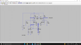
I was just thinking - its not the act of probing the grid that's causing you the issue. Try the other side of the 1k's. If the plate voltages are not equal maybe you need a 100R pot from each cathode to the CCS - just a suggestion as in the simulation with R4 R5.
I was just thinking - its not the act of probing the grid that's causing you the issue. Try the other side of the 1k's. If the plate voltages are not equal maybe you need a 100R pot from each cathode to the CCS - just a suggestion as in the simulation with R4 R5.
Yes, the long measurement leads could cause oscillation, that’s something I considered as well, will start debugging tomorrow, thanks for the suggestion!
View attachment 1001061Just going with what Mr. SS is using and the plate resistors. I would probably use E88CC rather than ECC99 if the plate dissipation is OK and the supply voltage. Nearly pin compatible too with exception of heaters.
I actually started with the 6922 (E88CC) but only have two of those, I switched to ECC99 as the bias point is about the same and I have 8pcs of those, so it is easier to rule out if there’s an issue with a particular tube, as the sample size is greater. Unfortunately they all show the same thing and I didn’t want to change the heater configuration again so I left the ECC99 in as when I solve the issue for the ECC99 it will also be solved for the 6922 at which point I can switch back again.
Probably needless and maybe even insulting to ask if you measured it also with the first LTP tube and endtubes removed and endtube grid bias switched off.
Ha! I didn’t but since there’s no DC path, due to the coupling caps it shouldn’t matter, DC can’t pass the coupling caps either side of the ECC99 so its DC balance point is not affected by what happens behind or in front of it.
P.s. first thing to try tomorrow morning is remove the global feedback loop, as if it is an oscillation that will most certainly remedy that, unless it is a local oscillation which I don’t believe is the case.
- Home
- Amplifiers
- Tubes / Valves
- Cascoded 12AX7 LTP - Stupid good performance?