That's a nice drawing, do you have the exact reference for fig. 4?Just after the Earth cooled Vacuum Toob Cascode Amplifiers were common. There are three common ways to connect stacked triodes. The example taken from Audio magazine shews each of them.
Maybe there is a electrolytic action between the nails and the wood which gives a wrong indication on the meter. Maybe put high voltage on one nail and low on the other and measure current. Mind its going to be in the uA region. Gad its sorted.
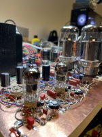
I built circuits like this in my early childhood. At that time I had access to lots of pine wood boards, an old Wen soldering gun, and all the parts that I could salvage from discarded TV's radios, and an occasional HiFi set.
I would drill holes into the wood then melt solder into the holes. These were my solder turrets. Surprisingly this worked reasonably well for my typical one to three tube attempts at making guitar amps. Oddly the performance would degrade over time with a reasonable working life of several months to maybe a year. This worked fine for a 9 year old kid with ADHD and very short attention span.
I later replaced the holes full of solder with brass furniture tacks primarily to reduce the parental complaints about the smell of burnt wood, even though my work was done outside in the Miami heat and humidity. Switching to brass tacks also improved the product lifetime.
Later in life I would come to understand that pine holds moisture, and some sort of electrolytic action occurs deep inside that moist wood. Some of my old dead, but not discarded projects had taken on a greenish brown hue in the area near the solder holes, and at least one developed a rather nasty carbon track which turned into burnt wood when I attempted to fire it up after a couple years of outdoor storage. The same thing can happen with the old brown phenolic PC and turret boards if left outside for a few years.
By this time I had graduated to using the solder lug strips removed from dead TV sets, so it really didn't matter.
nm I found it.That's a nice drawing, do you have the exact reference for fig. 4?
Kiebert, M. V., Cascode Preamp Improves Signal-to-Noise Ratio, Audio, October 1955, pp23-7+107.
https://worldradiohistory.com/Archive-All-Audio/Archive-Audio/50s/Audio-1955-Oct.pdf
OK Merlin, got it. Several years ago I downloaded several years of complete issues of Audio & other magazines of the era from that web site. All useful now, we can see how the ancients did it.🙂
I had a play with a measured OPT model. It was unstable. I've adjusted a few components added in a dominate pole and got the LF stable too. Hope you don't mind.
@baudouin0,
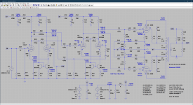
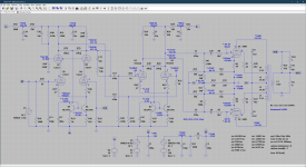
Thanks! In the meantime I’ve built a new prototype and it looker promising so I made some measurements as well. Please find the schematic etc. below. And yes, next step will be adding the cascode to the input stage, but I’m approaching this in stages.
Thanks! In the meantime I’ve built a new prototype and it looker promising so I made some measurements as well. Please find the schematic etc. below. And yes, next step will be adding the cascode to the input stage, but I’m approaching this in stages.
Attachments
-
 7687D06D-C8CE-4EBE-B766-5BF91AA58497.jpeg425 KB · Views: 142
 -
 FF2C482A-B846-424D-8964-65E63B8595D1.png538 KB · Views: 140
 -
 07AD6174-2A7E-43AA-897D-6C6A5E39516A.png120.6 KB · Views: 168
 -
 0AF387ED-D633-4831-B6D8-10954D1EC6CB.png214.4 KB · Views: 128
 -
 3DF07C40-4BFB-46AC-B427-5E57E0020CCB.png84.5 KB · Views: 120
Your doing very well with this. Keep an eye on the LF stability - I think I posted has lead-lag compensation in the NFB which will solve this if you run into issues. I see you drilled hole in the copper. When doing the FM tuner I used upside down pieces of cut stripboard and super glue onto the copper clad board. I've been using Kicad PCB layout recently and its real easy to get a PCB made for very little - used jlcpcb. I think you have a good design as it stands actually.
Last edited:
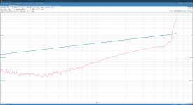
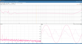
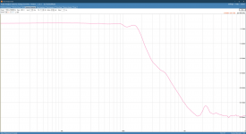
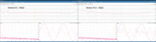
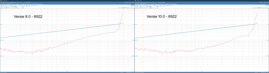
Alright, spent some time today getting the cascode input stage up and running and made some quick, preliminary measurements, comparing to the version without the cascode. I must say I’m pleasantly surprised to see a good enough correlation between the simulation and the real world results. Granted they’re not similar, but the cascode input stage sees a similar boost in performance on the bench as in the simulator.
There’s work to be done still though, as some of the voltages don’t yet line up with the simulation so I’ll have to revisit both the prototype and the simulation to see where the discrepancy comes from.
As always suggestions are more than welcome!
There’s work to be done still though, as some of the voltages don’t yet line up with the simulation so I’ll have to revisit both the prototype and the simulation to see where the discrepancy comes from.
As always suggestions are more than welcome!
Attachments
Yep something slightly adrift. I would put C20 to ground rather than HT myself. If you can get back to .5ma through each 12ax7 then you don't need that -10V supply and the current mirror can go back to ground.
Thanks! C20 on the HT sees better PSRR as any ripple on the supply rail gets coupled into the grids and thus the cathodes see the inverse of that causing for at least a 40dB improvement in PSRR. I’ll have a look at the current mirror tomorrow, I was worried it would run out of voltage with the cascode hence the negative supply.Yep something slightly adrift. I would put C20 to ground rather than HT myself. If you can get back to .5ma through each 12ax7 then you don't need that -10V supply and the current mirror can go back to ground.
Add say 100000k from each cascade plate-cathode connection to ground. LT spice does not like this and calculates the wrong DC operating point.
Good point. If your at the same DC current then you should not run out of voltage although the plate is lower. You can go down to some quite low voltages with the current mirror.
Yes, I wanted to do that, good suggestion!Add say 100000k from each cascade plate-cathode connection to ground. LT spice does not like this and calculates the wrong DC operating point.
Yep you are correct but you can go right down to say 200mV across the current mirror resistors and it will still track. You don't need much signal on the first cascade so you could go higher with the grid. Whether you need the cascade is debatable. With 17-20dB NFB you already have enough gain I think.
For just the cascode you mean?A 12ay7 is another alternative.
- Home
- Amplifiers
- Tubes / Valves
- Cascoded 12AX7 LTP - Stupid good performance?