Inductance may also be level dependent and be much lower at test equipment levels
I’ve managed to display magnetic hysteresis loop variation against applied signal level
Cartridge dynamic behaviour
(Un)fortunately, freq sweeps with level from approx 1mV RMS to 690mV RMS across the coil, translated to almost no difference in either the response or the impedance plots.
Stanton MK V
Cartridge dynamic behaviour
Cartridge dynamic behaviour
Shure M97xE
Cartridge dynamic behaviour
Cartridge dynamic behaviour
Pickering 950EE MK II
Cartridge dynamic behaviour
Cartridge dynamic behaviour
Audio-technica AT110E
Cartridge dynamic behaviour
Cartridge dynamic behaviour
AKG P8ES
Cartridge dynamic behaviour
Cartridge dynamic behaviour
Denon DL-103
Cartridge dynamic behaviour
Cartridge dynamic behaviour
George
Hi George,
Started re-reading this as getting close to having something working and realised that there is a loose end that I have a part in not tying up wrt to comparing the solid and split pin ortofons and if the eddy current loss is real. Cartridge dynamic behaviour
Started re-reading this as getting close to having something working and realised that there is a loose end that I have a part in not tying up wrt to comparing the solid and split pin ortofons and if the eddy current loss is real. Cartridge dynamic behaviour
Hi George,
Started re-reading this as getting close to having something working and realised that there is a loose end that I have a part in not tying up wrt to comparing the solid and split pin ortofons and if the eddy current loss is real.
If these eddy current loss, and frequency dependent inductance effects are part of the "sound" what can the pre-amp do about it? In experimenting with the Pass Labs M2 idea (gain via a step up transformer) the effect is easily measured and quite substantial.
From what I gather many folks just tweak the loading by ear (reading some of the older posts).
Hi George,
Started re-reading this as getting close to having something working and realised that there is a loose end that I have a part in not tying up wrt to comparing the solid and split pin ortofons and if the eddy current loss is real. Cartridge dynamic behaviour
Bill
I looked at the brochure https://www.ortofon.com/media/15182/ortofon-series-500-mm-cartridges-brochure-page-1.jpeg
and then at their MI/MM patents
MAGNETIC STEREOPHONIC PHONOGRAPH PICKUP
Replaceable stylus for stereophonic phonograph pickup - Fonofilm, Industri A/s
I am not sure what they refer to in the brochure by the “pole pin”
Do they mean in the patents the moving element 17 (fig. 1, 2), which in one implementation is a soft tubular armature (MI fig.4) , in another implementation is a tubular magnet (MM fig.5)?
Or
Do they mean the fixed annular permanent magnet element (14)?
In experimenting with the Pass Labs M2 idea (gain via a step up transformer) the effect is easily measured and quite substantial.
What effect Scott?
George
Folks do just randomly glom around with loading until it is pleasant. However the confusion is that, whilst there are many measurements of the dip, when LD ran a frequency scan using his transamp on a solid pin ortofon no dip was found. So unless this is very level dependent there is something strange. Or at least a loose end.
Georges measurements do seem to indicate that the coil system FR could be a driver of this, but we need to measure two ortofons on his rig for that. Which I happen to have. If this is the case neatly ties things up.
If it is not affected by level then a simple shelf will fix it.
George: Figures 1 and 2 of the 500 series brochure. OM has a solid pin (as do DJ lines) Super OM, 5x0 and 2M have the split pole pin.
What effect Scott?
George
Level dependent frequency response, same thing measured on L/R/C equalizers that use cored L's (+-3dB depending on level). Easily heard even by my ears.
Scott, you are the first from whom I read that a head step up transformer varies fr resp that much (+/-3dB) depending on signal level.
Ditto for the L/R/C RIAA equalizers with cored Ls.
Bill, again (if you know). Where in the patents drawings is the “pole piece” mentioned in the brochure’s fig 1, 2.
George
Ditto for the L/R/C RIAA equalizers with cored Ls.
Bill, again (if you know). Where in the patents drawings is the “pole piece” mentioned in the brochure’s fig 1, 2.
George

Scott, you are the first from whom I read that a head step up transformer varies fr resp that much (+/-3dB) depending on signal level.
Ditto for the L/R/C RIAA equalizers with cored Ls.
George, it's the Edcor inter-stage that they are using on the DIY Pass M2. I have not yet determined how audible this is.
I posted the equalizer results here a while back (they are now lost and I would have to recreate them from the raw data) they were audible. Remember, level dependent frequency response equals IM distortion.
Last edited:
Thanks Bill. In the patent, these four legs (item 10) are described as solid cylinders and not as hollow tubes (permalloy)
Scott, I have missed that post in which you showed the measurements. I will search for it. Thanks 9although I am more interested in the fr resp variations from the transformer 🙂 )
George
Scott, I have missed that post in which you showed the measurements. I will search for it. Thanks 9although I am more interested in the fr resp variations from the transformer 🙂 )
George
They were solid cylinders in the VM series (which was the design the patent was written for) and OM series. The 500 series were where the split pin was introduced and since then they have made examples of both solid and split just to confuse everyone!
Doesn't help that the FR plot for the SME30H (solid pin) does not show the droop that they have in the 500 series brochure. BUT they are using a very healthy 400pF load and SME did put extra C in the arm base for ortofons.
Doesn't help that the FR plot for the SME30H (solid pin) does not show the droop that they have in the 500 series brochure. BUT they are using a very healthy 400pF load and SME did put extra C in the arm base for ortofons.
Attachments
Should also note that the AKG P8 and OM share a lot of similarities. I have heard say that AKG were first, but ortofon got the patent out. Not sure if that is true and not looked inside the P8 to see if its wound the same way.
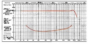
Thanks. (Un)fortunately, even 1mv cartridge output represents an untrackable high programme level at, say, 10kHz.(Un)fortunately, freq sweeps with level from approx 1mV RMS to 690mV RMS across the coil, translated to almost no difference in either the response or the impedance plots.
At issue is levels perhaps -40dB below that.
[oops scratch that, got RIAA correction the wrong way round.]
LD
Last edited:
OK I agree that your curves show level is not coming into it, surprising as the (tiny) permalloy poles are incredibly easy to saturate.I’ve managed to display magnetic hysteresis loop variation against applied signal level
Cartridge dynamic behaviour
(Un)fortunately, freq sweeps with level from approx 1mV RMS to 690mV RMS across the coil, translated to almost no difference in either the response or the impedance plots......
George
What is hard to explain is that the impedance rises linearly with frequency, like an inductor, but the phase is NOT 45 when real and imaginary are equal and that the phase is topping out at about 60 when the impedance is still rising smoothly. I cannot think how to model this.
I cannot think how to model this.
Yes, several plots have been presented here that are very non-minimum phase.
1mV f sweep represents programme levels ref 0dB 5mV@1kHz:
0dB@100Hz, -13.9dB@1kHz, and -28dB,@10kHz
Which is probably slightly on the bass warm side of realistic normal level.
One could look at lower levels if there was any sign of difference, but I don't think so and happy to accept this as evidence of no effect.
LD
0dB@100Hz, -13.9dB@1kHz, and -28dB,@10kHz
Which is probably slightly on the bass warm side of realistic normal level.
One could look at lower levels if there was any sign of difference, but I don't think so and happy to accept this as evidence of no effect.
LD
Which means that the standard frequency response model based on the cable and preamp capacitance resonating with cartridge inductance is invalidYes, several plots have been presented here that are very non-minimum phase.
Not so much invalid as only part of the story. Even the more advanced cart models proposed seem to miss things. It seems that cantilever resonance is considered the Deus ex Machina that can make a model work to reality.
Now here is an added conundrum. Apologies for linking to a German language website but Google translate does do the job, plus its not the text I am interested in Test Audio-Technica VM740ML: die noble Art zu Horen – LowBeats
They compare the AT 540 and 740 cartridges. Same stylus insert just differing bodies. same coil L and R, same tracking ability but the 740 has the classic midrange dip and the 540 doesn't. Digging deeper I note a 20% higher output, so maybe we can assume different cores in the 740.
Check the AT website and both carts have the same output spec! OK we knew AT are a bit fast and loose with fact checking, but something is screwy there.
(and yes I know a nice presence dip is often liked).
I don't see what the cantilever can do to shift electrical phase of a LR network based on fixed coils on fixed polesNot so much invalid as only part of the story. Even the more advanced cart models proposed seem to miss things. It seems that cantilever resonance is considered the Deus ex Machina that can make a model work to reality.
- Status
- Not open for further replies.
- Home
- Source & Line
- Analogue Source
- Cartridge dynamic behaviour