@JP,
With your wonderful Cart you have made recordings from the Ortofon Test record with 33 1/3 and 45 rpm.
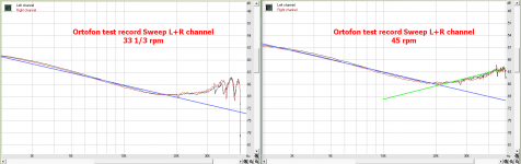
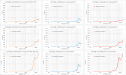
What stroke me is that with both recordings, the reversal from 10dB/dec downhill to 10dB/dec uphill lies at ca. 20kHz which does not seem logical when this would be record related, see image below.
In that case I would have expected a shift of this turning point from 20kHz@33rpm to 27kHz@45rpm.
In the carts I have tested for Bill, Cartridge dynamic behaviour there was also a nice Technics Cart with a very wide FR just like yours, but seemingly not completely happy with the usual 150pF//47K, also going uphill as from 20Khz.
With 150pF//21K it was nice and flat.
Since not knowing the capacitance of your cabling, this could amplify the upgoing FR even further if larger than 150pF.
Anyhow, my question is whether it would be possible for you to load the Cart with ca 21K in combination with a low to medium capacitance interconnect and to repeat the recordings fot 33 1/3 and 45 rpm.
That would give extra valuable info regarding the test record.
Hans
With your wonderful Cart you have made recordings from the Ortofon Test record with 33 1/3 and 45 rpm.
What stroke me is that with both recordings, the reversal from 10dB/dec downhill to 10dB/dec uphill lies at ca. 20kHz which does not seem logical when this would be record related, see image below.
In that case I would have expected a shift of this turning point from 20kHz@33rpm to 27kHz@45rpm.
In the carts I have tested for Bill, Cartridge dynamic behaviour there was also a nice Technics Cart with a very wide FR just like yours, but seemingly not completely happy with the usual 150pF//47K, also going uphill as from 20Khz.
With 150pF//21K it was nice and flat.
Since not knowing the capacitance of your cabling, this could amplify the upgoing FR even further if larger than 150pF.
Anyhow, my question is whether it would be possible for you to load the Cart with ca 21K in combination with a low to medium capacitance interconnect and to repeat the recordings fot 33 1/3 and 45 rpm.
That would give extra valuable info regarding the test record.
Hans
Attachments
As you measured the Great grandfather of JPs cartridge there likely is a family resemblance as my (limited) understanding is that the MK3 and MK4 focussed on suspension and moving mass optimisation but the generator was very similar.
Hans I’m back at the house weekend after - in London till Monday.
JP, thanks for reacting so rapidly.
I used a straight amp so far fed by an extremely noisy SMPS switching at 50kHz.
Replacing this power supply by batteries led to a far better result.
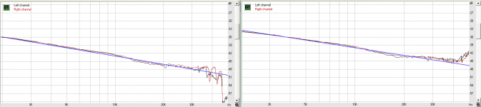
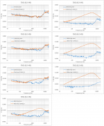
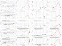
Below are the FR at 33 1/3 left and 45rpm at the right, produced in exactly the same way as I did with your two files.
The 33 1/3 version still has the dreadful anomalies above 30kHz, but up to 30kHz the FR is within +/- 1dB with no uplift from 20kHz.
The 45 rpm version is straight up to 40kHz within +/- 1db.
From 40kHz and up, I also have a 10dB/dec upwards going slope.
These large differences between our Carts are the reason why I asked you to try a different loading of your Cart.
Hans
Attachments
Ortofon Super OM10_R channel.
Now for distortion testing of the fixed part of the cartridge generator (coil and magnetic core)
I decided to use the “stepped sine” test of REW.Distortion Graph
20Hz-20kHz, 24 points per octave i.e. 229 frequencies (8minutes per run). 24bit, 96kHz SR.
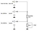
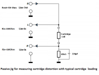
Cartridge coil in series with the output of the soundcard.
For every signal level there were two test runs. One with the cartridge and one with a short in place of the cartridge.
All distortion % numbers are rel to fundamental stepped sine level at each freq step.
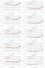
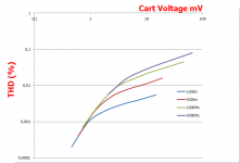
2nd, 3rd and THD start rising above circa 600Hz for signal levels higher than 40mVrms but even at 320mVrms, the THD (mainly 3rd) doesn’t rise above 0.05%.
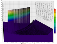
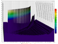
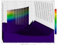
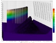
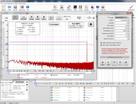
Attachment 7 is a waterfall of distortion test run at 320mVrms with the cartridge at the test terminal and attachment 8 is with the short in place of the cart.
At low signal levels, cartridge distortion can not be distinguished from what the short shows.
Only btn 1kHz and 5kHz there is a slight rising which required more detailed investigation. 96 points per octave (25 minutes for a run) and an application of a light running averaging produced a more clear picture (attachment 9). The distortion increase is not more than 0.025%
George
Now for distortion testing of the fixed part of the cartridge generator (coil and magnetic core)
I decided to use the “stepped sine” test of REW.Distortion Graph
20Hz-20kHz, 24 points per octave i.e. 229 frequencies (8minutes per run). 24bit, 96kHz SR.
Cartridge coil in series with the output of the soundcard.
For every signal level there were two test runs. One with the cartridge and one with a short in place of the cartridge.
All distortion % numbers are rel to fundamental stepped sine level at each freq step.
2nd, 3rd and THD start rising above circa 600Hz for signal levels higher than 40mVrms but even at 320mVrms, the THD (mainly 3rd) doesn’t rise above 0.05%.
Attachment 7 is a waterfall of distortion test run at 320mVrms with the cartridge at the test terminal and attachment 8 is with the short in place of the cart.
At low signal levels, cartridge distortion can not be distinguished from what the short shows.
Only btn 1kHz and 5kHz there is a slight rising which required more detailed investigation. 96 points per octave (25 minutes for a run) and an application of a light running averaging produced a more clear picture (attachment 9). The distortion increase is not more than 0.025%
George
Attachments
-
 9 0.5mV bump in THD btn 1kHz-5kHz (96PPO).png55 KB · Views: 134
 -
 8 320mVrms-short waterfall.png602.6 KB · Views: 150
 -
 7 320mVrms-S-OM10_R waterfall.png576.3 KB · Views: 148
 -
 6 Ort Super OM10_R THD, H2, H3.png111 KB · Views: 157
 -
 5 Ort Super OM10_R THD logarithmic scale.png242.9 KB · Views: 148
 -
 4 REW settings.png242 KB · Views: 153
 -
 3 schematic of distortion jig.png11.3 KB · Views: 270
 -
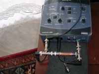
 2 short.JPG689.7 KB · Views: 249
 -
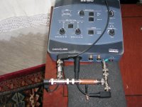
 1 Super OM10.JPG672.7 KB · Views: 265
Wow George,Now for distortion testing of the fixed part of the cartridge generator (coil and magnetic core)
George
What an impressive amount of work, chapeau.
Did it match your expectations ?
Looking at the images it seems that the Cart was loaded with the 1Meg//?pF input of the EMU, in that case very little current flowing through the Cart.
If so, was there a reason why you did not load the Cart with 47K//150pF, reflection the situation when playing ?
Hans
+1
@George. My cartridges are now with someone else whose listening to them (and may even buy one). Did you want any more examples to measure to compare against Hans' meausurements?
@George. My cartridges are now with someone else whose listening to them (and may even buy one). Did you want any more examples to measure to compare against Hans' meausurements?
Thanks for the good words
Hans, I hadn’t thought of the extra current through the coil when loading it.
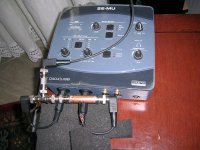
Will the setup be like the attachment ? (I use this for freq resp sweep testing)
Good to know. At last there is one normal person among us.
No, thanks Bill. Now Hans impedance measurements and mine are in agreement and Hans test equipment is really good.
Besides I struggle to keep my marriage alive. My wife is about to lock me out of our bedroom. She is jealous of those cartridges I spend my days with.
George
If so, was there a reason why you did not load the Cart with 47K//150pF, reflection the situation when playing ?
Hans, I hadn’t thought of the extra current through the coil when loading it.
Will the setup be like the attachment ? (I use this for freq resp sweep testing)
My cartridges are now with someone else whose listening to them
Good to know. At last there is one normal person among us.
Did you want any more examples to measure to compare against Hans' measurements?
No, thanks Bill. Now Hans impedance measurements and mine are in agreement and Hans test equipment is really good.
Besides I struggle to keep my marriage alive. My wife is about to lock me out of our bedroom. She is jealous of those cartridges I spend my days with.
George
Attachments
Yep, that’s what I meant.Hans, will the setup be like the attachment ? (I use this for freq resp sweep testing)
But keep it simple, 5mV will do to start with .
It seems unlikely that a lower level will produce more distortion.
😂Good to know. At last there is one normal person among us.
On first listen the 205CII-L has impressed him the most. He has already bought my AT-25 (the integrated headshell version of the AT-22 Hans tested) as having two is an extravagance I don't need. The 205 is a challenge in a way with its low 1.8mV output (0.9mV if you put the std 205 stylus in). Replacement stylii are not cheap to the point its cheaper to go to expert stylus for a retip. Luckily this one is unworn so I have many years before I have to worry about that.Good to know. At last there is one normal person among us.
Hans is right.
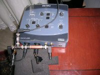
There is difference in distortion when cartridge is loaded with 47kOhm//220pF
Same cartridge and channel (Ortofon Super OM10_Rch) as with the previous post.
Again, attachment 7 is a waterfall of distortion test run at 320mVrms with the cartridge at the test terminal and attachment 8 is with the short in place of the cart.
George
Attachments
-
 8 320mVrms-short_loaded.png579.6 KB · Views: 119
 -
 7 320mVrms-S_OM10_R_loaded.png557.8 KB · Views: 122
 -
 6 THD-H2-H3 vs level.png127.3 KB · Views: 134
 -
 5 THD vs level.png170.5 KB · Views: 238
 -
 4 REW settings.png242 KB · Views: 237
 -
 3 schematic of distortion jig with typical cartridge loading.png13 KB · Views: 237
 -
 2.JPG642.1 KB · Views: 242
 -
 1.JPG653.7 KB · Views: 241
Hi George,Hans is right.
There is difference in distortion when cartridge is loaded with 47kOhm//220pF
Same cartridge and channel (Ortofon Super OM10_Rch) as with the previous post.
Again, attachment 7 is a waterfall of distortion test run at 320mVrms with the cartridge at the test terminal and attachment 8 is with the short in place of the cart.
George
Great job, I hope all doors in your house are still ...... 🙂
Anyhow, interesting that the distortion seems to be dominantly third harmonic, meaning that the distortion is symmetrical, probably saturation of the core ?
Because the ever increasing impedance of the Cart with upgoing frequencies, voltage over the Cart in your setup is not constant but relatively low at low frequencies, rising with higher frequencies.
I don't know what Fs you used, but it almost seems as if this was quite low because distortion makes a turning point at 4kHz, which otherwise seems difficult to explain ?
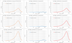
From your images I have tried to make a translation with a bit of interpolation from constant voltage over the combo Cart +47K//220pF to a known voltage over just the Cart, see image below.
Looking at a typical distortion from JP's Cart, made by Scott from the 3.14cm/sec Ortofon CV recording, Cartridge dynamic behaviour the level of the 3rd harmonics in your measurements at 3mV are almost the same as in Scotts image.
Could this possibly mean that the motor produces just the 2nd harmonics and the non linearity of the coil the 3rd harmonics ?
Hans
Attachments
I am suspecting magnetic core non linearities as the route of distortion.
I chose the moderately low 40mVrms signal level and did some more step sine test runs, this time energizing both coils of the Super OM10 with the hope of increasing the magnetic flux in the core.
What is shown (5 lines) is:
1. R ch coil only
2. R and L in parallel in phase
3. R and L in parallel out of phase
4. R and L in series in phase
5. R and L in series out of phase
Loading is as before with 47kOhm and 205pF external components. I haven’t measured yet the capacitance of the jig, I will do later. This jig is versatile but I think I have to build a simpler one with less connectors. This on another post next day.
George
Attachments


George,I am suspecting magnetic core non linearities as the route of distortion.
I chose the moderately low 40mVrms signal level and did some more step sine test runs, this time energizing both coils of the Super OM10 with the hope of increasing the magnetic flux in the core.
What is shown (5 lines) is:
1. R ch coil only
2. R and L in parallel in phase
3. R and L in parallel out of phase
4. R and L in series in phase
5. R and L in series out of phase
Loading is as before with 47kOhm and 205pF external components. I haven’t measured yet the capacitance of the jig, I will do later. This jig is versatile but I think I have to build a simpler one with less connectors. This on another post next day.
George
I'm a bit confused.
Could it be that in your results you have switched the parallel and series results.
With coils in series, level per coil drops by 6dB, which should result in much less distortion, whereas coils in parallel have the same level as a single coil where I would expect the same distortion as the single coil.
Switching your results does exactly what I would have thought.
Hans
George,
I'm a bit confused.
Could it be that in your results you have switched the parallel and series results.
Hans
I just confirmed I did a sillier mistake than the one you mentioned.
I got the polarity of the L channel wrong, therefore what was written as “in phase” is actually “out of phase” and vice versa.
Therefore, instead of swapping labels I will repeat that test and repost the hopefully correct measurements (double checking not to switch the parallel and series results)
George
Looking again and more closely to the third harmonic, I noticed that I the harmonics measured by George are 20dB below those in Scott's Image that I referred to.Hi George,
From your images I have tried to make a translation with a bit of interpolation from constant voltage over the combo Cart +47K//220pF to a known voltage over just the Cart, see image below.
Looking at a typical distortion from JP's Cart, made by Scott from the 3.14cm/sec Ortofon CV recording, Cartridge dynamic behaviour the level of the 3rd harmonics in your measurements at 3mV are almost the same as in Scotts image.
Could this possibly mean that the motor produces just the 2nd harmonics and the non linearity of the coil the 3rd harmonics ?
Hans
So not only the measured second but also the third harmonics has most likely to be accounted to the Carts motor.
Non linearity of the coil producing third harmonics, seems to play a neglectable role, at least for this Ortofon super 10 Cart.
Hans
Non linearity of the coil producing third harmonics, seems to play a neglectable role, at least for this Ortofon super 10 Cart.
The simple groove/stylus geometry plays a large role here if you are looking at an actual LP track. The THD plots should note the stylus geometry at least for information purposes. If someone could do a plot with the same cart and two very different stylus geometries it might be interesting. I personally doubt the THD of the test LP grooves is stellar.
- Status
- Not open for further replies.
- Home
- Source & Line
- Analogue Source
- Cartridge dynamic behaviour