Far more nefarious than that. I expect my shipping agent to buy at least one before they come back!
Far more nefarious than that. I expect my shipping agent to buy at least one before they come back!
Bill,
I very much doubt whether they are going to buy.
Customs were extremely alarmed by your shipment, parcel was full of Xray stickers and the parcel had been opened.
In this MP3 era, they probably had no idea what Carts are, so expect no big deal. 😀
Hans
Bill,
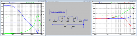
This is the first run of a totally different Cart that you just sent me, the Technics 205C-IIX.
Very low inductance Lc=41.5mH at LF, decreasing rapidly at higher frequencies, a very low Rc=32.5 Ohm and a relatively high Fres.
Interesting Cart.
Hans
This is the first run of a totally different Cart that you just sent me, the Technics 205C-IIX.
Very low inductance Lc=41.5mH at LF, decreasing rapidly at higher frequencies, a very low Rc=32.5 Ohm and a relatively high Fres.
Interesting Cart.
Hans
Attachments
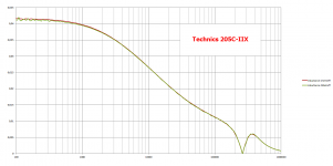
Here is the Technics 205C-IIX, a hard nut to crack.
Termination with voltage amp was as advised 150p//47K.
However with 150p//21k the FR is flat within 0,2dB up to 100kHz.
The Cart seems less suited for use in combination with a virt. gnd amp.
With an extra pole at 12usec the FR was within +/-2dB up to 30kHz.
Hans
Termination with voltage amp was as advised 150p//47K.
However with 150p//21k the FR is flat within 0,2dB up to 100kHz.
The Cart seems less suited for use in combination with a virt. gnd amp.
With an extra pole at 12usec the FR was within +/-2dB up to 30kHz.
Hans
Attachments
Blimey. Well this was released with the express purpose of having less FR deviation into standard phono inputs. Which the market did not seem bothered by. But that is really interesting. Thank you.
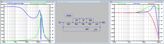
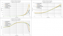
And now the AT22.
As with the Technics, although completely different, it also doesn't seem to feel happy with 150pF//47k.
With 150pF/22k, FR is flat to 43kHz, see green line in the image below at the right.
With 40pF//47K FR is even flat to 70kHz, see red line, possible when built into the TT's plinth to keep capacitive load low.
And Virtual Gnd does not seem the best way to go even with an additional 8usec pole, as shown in the left image.
Hans
Attachments
Less suprised after the technics result, but still intrigued. Looks a perfect candidate for the phantom powered head amp!
@Bill,
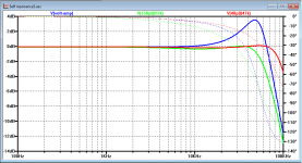
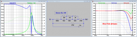
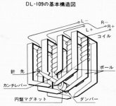
here is the last of the Mohicans, the replacement circuit of the DL-109. looking nice and flat up to 20kHz.
Still keep repeating that for all Carts the replacement circuits have been driven with flat spectrum voltage sources as if the motor has a non frequent dependent output, which of course is an unknown but very important factor in the overall transfer curve.
So that motor part has still to be analysed.
When knowing the overall FR, the motor properties will become visible by subtracting the transfer curves of the replacement circuits.
Still looking forward at further steps in better understanding MM Carts.
Hans
P.S. Still haven't got an answer from Ortofon referring their Test Record.
I'll send them a reminder next week.
Attachments
Hans
You are doing a great service to the community by constructing and communicating these equivalent circuits.
Congratulations for your work.
George
You are doing a great service to the community by constructing and communicating these equivalent circuits.
Congratulations for your work.
George
Hans
You are doing a great service to the community by constructing and communicating these equivalent circuits.
Congratulations for your work.
George
Thank you George, but don’t be modest, you are contributing your share also.
Hans
Just as additional info to my Cart testing.
From all Carts I only used the Right channel because the minus pin is connected to the body, thereby acting as a shield as it also does for both channels in normal use.
So I didn’t see any reason to test the Left channel without the body shielding.
Expect to measure a lower par. capacitance and a higher Fres when testing the Left channel without body shielding in this abnormal situation.
Hans
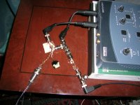
Talking about shield attached channel or not, here are what I measured with the two voltmeter method.
The two high Z inputs of Mogen’s E-MU soundcard serve as meters and phase difference indicators through REW SW (192kHz SR, ASIO drivers).
If owner agrees, Dual and Super OM10 may be later sent to Hans for having them tested by him as well because there is difference btn his and mine impedance results on the Super OM10.
George
Attachments
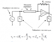
George,Talking about shield attached channel or not, here are what I measured with the two voltmeter method.
The two high Z inputs of Mogen’s E-MU soundcard serve as meters and phase difference indicators through REW SW (192kHz SR, ASIO drivers).
If owner agrees, Dual and Super OM10 may be later sent to Hans for having them tested by him as well because there is difference btn his and mine impedance results on the Super OM10.
George
Could you test your measuring set with resp a 1k, 10k and 100k resistor instead of the Cart over the same frequency range ?
Hans
It is also possible I can route any of the cartridges Hans has baselined to you George for comparison. Always possible that there is some manufacturing tolerance at play but I would not expect that to be more than a few percent on an MM.
The DL-109 is another intrigue. It was possibly the most complex generator ever in MM circles with 12 poles but clearly CD4 replay was not high on the designers agenda. not suprising as I think it was another radio station commission.
Thank you both for your work on this to date. Ball firmly in my court now 🙂
Attachments
George,
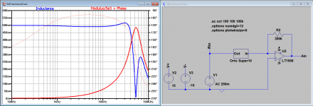
I inserted the equivalent circuit for the OM10 in your measuring setup.
See image below.
I used a LT1056 Fet Op-amp, similar to your LF356.
There is no difference in the results between my and your way of measuring, so I wonder what the EMU could be contributing.
Hans
I inserted the equivalent circuit for the OM10 in your measuring setup.
See image below.
I used a LT1056 Fet Op-amp, similar to your LF356.
There is no difference in the results between my and your way of measuring, so I wonder what the EMU could be contributing.
Hans
Attachments
George,
Could you test your measuring set with resp a 1k, 10k and 100k resistor instead of the Cart over the same frequency range ?
Hans
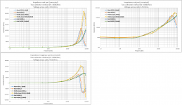
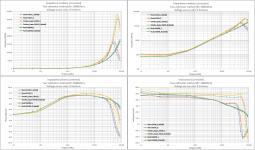
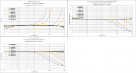
Yes and a few more, see first attachment below.
This is a standard procedure I follow to test for errors with cal resistors.
The error for each resistor value at the frequency of applicability is not big, not more than 5% (except at 10Hz). For the phase , not more than 10 degrees.
Then I extract the corresponding correction factor and I apply it on the carts measurement. I’ve used 9 resistors from 500Ohm to 300kOhm. The in-between values are a subject of interpolation.
Second attachment is carts measurement before correction is applied.
On the previous post I attached the corrected measurements.
It takes time to do all the data entry (*) and then check for silly mistakes on the diagrams, that’s why I delay in posting results
George
(*)for this exercise: 432 numbers written down on paper and typed into Excel for the 9 cal resistors, another 288 numbers for the 3 carts

Attachments
Thanks Hans, good to know there is no incompatibility issue btn the two methods.I inserted the equivalent circuit for the OM10 in your measuring setup.
There is no difference in the results between my and your way of measuring, so I wonder what the EMU could be contributing.
I do not think the problem is with the E-MU. Look back at post #1195. The same two- voltmeter method but no E-MU soundcard used there. The Z modulus (no phase data) is the same. The Super OM peak is at 70-80kHz.
Cartridge dynamic behaviour
Then, with another kind of measurement, see post #524, showing the self-resonance frequency close to those found with the two-voltmeter test.
Cartridge dynamic behaviour
I have also made auto impedance sweeps which show essentially the same picture ( I don’t show them because I haven’t performed the correction procedure on them yet).
For the moment, I tend to think that the difference in res freq btn the two Super OM 10 carts has to do with that they are physically different.
If Bill gives the OK, I will send Dual and Ortofon carts to you (after finishing distortion vs signal level tests), so you can test them and we will finally see what is going on.
George
George,Yes and a few more, see first attachment below.
This is a standard procedure I follow to test for errors with cal resistors.
The error for each resistor value at the frequency of applicability is not big, not more than 5% (except at 10Hz). For the phase , not more than 10 degrees.
Then I extract the corresponding correction factor and I apply it on the carts measurement. I’ve used 9 resistors from 500Ohm to 300kOhm. The in-between values are a subject of interpolation.
Second attachment is carts measurement before correction is applied.
On the previous post I attached the corrected measurements.
It takes time to do all the data entry (*) and then check for silly mistakes on the diagrams, that’s why I delay in posting results
George
(*)for this exercise: 432 numbers written down on paper and typed into Excel for the 9 cal resistors, another 288 numbers for the 3 carts
That was a huge amount of work for you to do. 👍
I wonder what can be the cause of those errors because I see no direct reason.
I only checked the difference between both channels with a 0 Ohm connection between them, but now I will also check for 1k, 10k and 100k.
Hans
- Status
- Not open for further replies.
- Home
- Source & Line
- Analogue Source
- Cartridge dynamic behaviour