so I don't think it can play any role at all, do you agree ?
Yes, I would also think the surface noise a high frequencies would have a flat spectrum. It looks like there is a slight break at 10k, coincidence? Another scenario these guys went back and forth to correct for some speed related component of tracing error, need LD on this one. In that case sweeps might show the same anomaly.
Last edited:
Riaa pre-emphasis errors, caused by playing at different speeds, were corrected in the black line in the images at #808.Except RIAA pre-emphasis is there for just that reason. The sampling artifact (33 play of a 45 is essentially re-sampling at a lower frequency) is appealing but I don't see it acting the way it is. It's also worth exploring if the sinc() response correction has anything to do with this (if the noise is actually digitally generated).
Image below shows the calculated deviation that's being used for drawing the black lines.
The sinc correction tip is an interesting one. The question is though at what frequency the digital noise file was created. To get >30kHz on the calibration record, it must have been at least 96kHz.
To correct for the sinc attenuation while reconstructing a 96kHz file, correction at 30kHz should be ca. 1.5dB .
Now playing such a file at lower speeds, would result in overcorrection, resulting in a curve going upwards instead of downwards.
That's the opposite of what we see.
I'll try to find out what sample frequency was used on the calibration disk and how this can possibly interfere with the results.
Hans
Attachments
Correct, surface noise has an 1/f character, and after a few hundred herz it's flat, however after being Riaa processed, its going down.Yes, I would also think the surface noise a high frequencies would have a flat spectrum. It looks like there is a slight break at 10k, coincidence? Another scenario these guys went back and forth to correct for some speed related component of tracing error, need LD on this one. In that case sweeps might show the same anomaly.
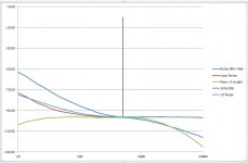
The image below shows how surface noise compares to 1/f noise and what it does after Riaa.
Hans
Attachments
George,Question. When we have the plot of the pink noise which consists from the pink noise engraving plus the surface noise, how can we mathematically deduct the two, so that we can estimate the pink noise alone from the composite effect curve?
George
Since the surface noise is >60 times smaller as the composite noise, it only contributes for 0.001dB to this composite noise, because:
20*log(1^2+(1/60)^2)=0.001dB
In other words, surface noise plays no role whatsoever.
Hans
Thank you Hans.
Aside from the magnitude difference which is big, are these two considered as correlated or non correlated noise?
George
Aside from the magnitude difference which is big, are these two considered as correlated or non correlated noise?
George
I have taken samples of 30 seconds this time, two times as long as before, now with 192k/24 instead of 96k/24.
And I have processed these recordings with overlapping FFT's from 16K to 256K length.
Noise spectra look a bit neater with smaller FFT's, but the FR's follow exactly the same curves, and also without the slightest signs of aliases between 48kHz and 96kHz.
So digital noise in combination with a brick wall filter must be produced at a very high frequency (384kHz?).
May be LD can shed his light on the subject why the recorded pink noise curves are differing at different rpm. My attempts to find any cause are exhausted at the moment.
Hans
The surface noise may be modulated by the signal, but I suppose you can regard it as non correlated.Thank you Hans.
Aside from the magnitude difference which is big, are these two considered as correlated or non correlated noise?
George
Hans
George,
Since the surface noise is >60 times smaller as the composite noise, it only contributes for 0.001dB to this composite noise, because:
20*log(1^2+(1/60)^2)=0.001dB
In other words, surface noise plays no role whatsoever.
Hans
You do need to correct for the effective bandwidth of the FFT and the effective differences in the band in question but anything larger than a 6 dB difference would drop out, correlated or not.
The interesting question in this is whether the response curve changes depending on content. Measured with sine waves gets one curve, measured with a composite waveform gets different results. (Madness lies down this path.)
Yeah - no such thing as a Neumann pole from all the research I've done on it. I believe it was Allen Wright (RIP) that first spoke about it and it took off from there.
You are correct. Allen found out that the cutting engineers were actually introducing a HF roll-off, to stop their cutting amplifiers from burning out.
So he came up with the '50kHz boost' to counter this ... so returning the signal coming off the vinyl groove, to RIAA theory.
That the cutting head amplifier is band limited should not be in question, but trying to compensate for it in the replay EQ is not a good move IMHO.
Why do you think it is not a good move to augment the standard RIAA response of a phono stage with Allen's HF boost?
Regards,
Andy
You do need to correct for the effective bandwidth of the FFT and the effective differences in the band in question but anything larger than a 6 dB difference would drop out, correlated or not.
The interesting question in this is whether the response curve changes depending on content. Measured with sine waves gets one curve, measured with a composite waveform gets different results. (Madness lies down this path.)
Hat tip to Jan who sent this link a few weeks ago:
FFT Scaling for Noise - Audio Precision
Scott, this seems the most likely explanation, one that confirms their own statements that they had to redo their records several times.Another scenario these guys went back and forth to correct for some speed related component of tracing error, need LD on this one. In that case sweeps might show the same anomaly.
That being the case, the conclusion could only be:
That Vinyl does not have a straight transfer function from cutter input to pre amp output and that this transfer function is also rpm dependant.
When being true, while investigating a Cart one cannot simply use a higher or lower rpm to extend the FR of a record without having to make the necessary corrections.
The correct pink noise we seem to have this far, when records being played at their intended speed:
A) from a 33 1/3 Adjust+ LP, producing pink noise from 20Hz to 2kHz within +/-0.5dB and
B) from a 45rpm CH Precision disk that's also correct within +/-0.5dB from 2kHz to 30kHz.
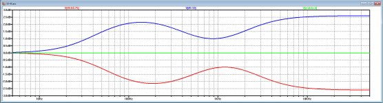
Playing the CH Precision record at a higher speed, means that a correction has to be made to correct the bump between 20kHz and 40kHz, see:
Cartridge dynamic behaviour
Hans
P.S. LD where are you ?
In the relevant images for 33 1/3 and 45rpm, pink noise signal and surface noise where processed the same way with the same Fs, same time window and same FFT settings.You do need to correct for the effective bandwidth of the FFT and the effective differences in the band in question but anything larger than a 6 dB difference would drop out, correlated or not.
No need for correction to be done IMO.
Because of your posting, I was made aware that I was dead wrong in thinking what a Neumann pole was.Area 42? Is this a new one?
Yeah - no such thing as a Neumann pole from all the research I've done on it. I believe it was Allen Wright (RIP) that first spoke about it and it took off from there.
That the cutting head amplifier is band limited should not be in question, but trying to compensate for it in the replay EQ is not a good move IMHO. Once you are beyond the audio band (> 20 kHz), you should just let things drop off gracefully.
A good test for this is a 10 kHz square wave through an inverse RIAA filter. The edges should start to show some nice rounding. If you have overshoot, your RIAA EQ is not accurate. Its a great way to test for RIAA compliance because its very sensitive to frequency anomalies at HF.
Instead of being an extra cutoff at 50kHz (T4=3.18usec) in the Riaa preamp, it is exactly the opposite, a boost to correct for the cutoff in the record cutter machine.
My comment on the Aurak having a Neumann pole was correct in that it has a pole at 50kHz, but for being a real "Neumann" it should have been a zero, exactly the opposite 😀
Thank you for making me aware.
Hans
The purpose of that pole in the Aurak original is just to keep overall bandwidth tidy, not to implement any RIAA or lathe compensation. Philosophically, I don't see the point of reproducing extreme ultrasonics, it just upsets the dog and there's nothing useful up there anyways, barring CD4 carriers etc.My comment on the Aurak having a Neumann pole was correct in that it has a pole at 50kHz, but for being a real "Neumann" it should have been a zero, exactly the opposite 😀
LD
My 2p worth is that there isn't playback rpm tracing dependency, beyond the obvious scaling of velocity and acceleration.Another scenario these guys went back and forth to correct for some speed related component of tracing error, need LD on this one. In that case sweeps might show the same anomaly.
The key element, stylus-groove interface friction coefficient doesn't change much if at all, and I verified this to my own satisfaction in the past. At very slow rpm there might be a difference, but not between 33rpm and 45rpm.
It's widely acknowledged in mechanics that sliding friction coefficient doesn't generally vary much with linear velocity. So a stylus can't really tell how fast the record is rotating, all it sees is an obstacle course which is the groove shape and the mechanical impedance looking into the cantilever.
Naturally, for a given groove shape, traceability is more demanding at 45rpm. But for the tracks at issue that is unlikely to present much challenge, and besides the anomalous result doesn't have an obvious mechanism via mistracing.
HTH!
LD
I agree, this extra pole in your case made sense and was clearly made visible over here (red vs blue line)The purpose of that pole in the Aurak original is just to keep overall bandwidth tidy, not to implement any RIAA or lathe compensation. Philosophically, I don't see the point of reproducing extreme ultrasonics, it just upsets the dog and there's nothing useful up there anyways, barring CD4 carriers etc.
LD
Cartridge dynamic behaviour
The point is just that I thought that this was a Neumann correction, but it turns out to be exactly the opposite, it's an anti Neumann pole 😀
Hans
My 2p worth is that there isn't playback rpm tracing dependency, beyond the obvious scaling of velocity and acceleration.
Naturally, for a given groove shape, traceability is more demanding at 45rpm. But for the tracks at issue that is unlikely to present much challenge, and besides the anomalous result doesn't have an obvious mechanism via mistracing.
So why then are the spectra so different when played at different speeds.
A cantilever resonance would pop up at the same frequency regardless of rpm, but there are no visible signs of such resonances.
Doesn't that mean that it's not the cartridge but only the record that is making the difference when played at a different rpm?
And as you say, a stylus only sees obstacles and has no idea about speed.
The thing that strikes me most of all is the repeatability of the curves, regardless of time window and FFT length. Reproduction accuracy is within +/-0.5dB.
And the curve at the intended speed of 45rpm is almost too nice to be true.
I agree with Scott, supported by CH Precision's statement, that this has been a back and forth correction process.
Even the Adjust+ LP, where the extracted pink noise curve looks nice and smooth, is only accurate within +/-0.5dB from 20Hz to 2kHz.
Hans
Well that is the $64m question.So why then are the spectra so different when played at different speeds.
Let's assume that RIAA correction modified for playback speed is correct, and that playback levels are not demanding for traceability/trackability.
Then the obvious factors that change with rpm are playback level and slew rate at cartridge output. And we are back to the OP question of whether f response is level dependent, and if so why...……….?
I had reached the conclusion previously that was likely true, and speculated it is due to generator magnetic loss performance at small levels, but that seems to have been shown false.
LD
Last edited:
Yes indeed, by changing the speed, playback level changes accordingly.Well that is the $64m question.
Let's assume that RIAA correction modified for playback speed is correct, and that playback levels are not demanding for traceability/trackability.
Then the obvious factors that change with rpm are playback level and slew rate at cartridge output. And we are back to the OP question of whether f response is level dependent, and if so why...……….?
I had reached the conclusion previously that was likely true, and speculated it is due to generator magnetic loss performance at small levels, but that seems to have been shown false.
LD
So it's either the level dependency of the Cart, the rpm dependency of the record or both.
For checking that the FR is level dependant, we need pink noise curves recorded at different levels on one and the same record, once on our diyAudio LP list.
So it seems like you say that we're back at square one.
The only thing shown at least to me is that a modern lightweight cantilever in a low compliance suspension doesn't show any signs of resonance.
Hans
At very slow rpm there might be a difference, but not between 33rpm and 45rpm.
That's what I would have thought. It's just too small a change and it's not the same thing as the change in groove geometry you get at inner grooves.
- Status
- Not open for further replies.
- Home
- Source & Line
- Analogue Source
- Cartridge dynamic behaviour