
Steenoe, curva, please calm down. Let's try and keep away from unfounded allegations, if you have comments to make, please keep them technical.
Sorry about that, couldn't help it.
Won't happen again🙂
Steen.
Ps. You are welcome to delete the offending post!
Won't happen again🙂
Steen.
Ps. You are welcome to delete the offending post!
steenoe said:
On the other hand, they would never have discovered this, anyway. Being too shortsighted.
I presume this is ultimately about music, isn't it??
Please correct me if being wrong here!
So, what I mean is: try the snubbered thing for yourself
If your music sounds better, well great.
If not, unplug......
Again, I think you over personalize it. Think about the thread. If it had started with "I tried it and think it sounds good but I don't see why it should work", the actual technical content of the tread would have likely been very much the same.
Whether the snubber circuit was tried or not tried, stayed plugged in or was unplugged, there still should be the same skepticism as to whether it is repeatable and to what extent it is generalizable, what the underlying model/theory is and what potential tests and measurements can be applied..
I don't think hypothesizing about potential motives or emotions is particularly helpful.
jackinnj said:A regulated power supply for a GC may provide some psychological compensation for the builder, however, so would a glass of porto...
It's good to see so many knowledge around here.
Specially, generalizing on regulators, and amplifiers.
The LM338 regulated PSU is an improvement over the low capacitance (1,000~1,500uf) in most systems, with most speakers.
If I had big 95db+ fullrange horns I wouldn't bother with this.
carlosfm said:
This is all new for you.😀
Not really
 😀
😀 (only if you reffer to building amps)
I don't know what kind of speakers you have ,but, I can only take all the "juice" from my speakers when I use amplifiers with big capacity. (like 40,000nF, 300VA transformer)
(I Know it depends on the type of music, cables you use, etc...)
But why should be diferent with this kind of amplifiers ?
The purpose was just to put focus on a peculiar thing which I thought at first, namely to have 100 nF in parallel with 100 nF + 1 ohms.steenoe said:Still I have a feeling this thread was started with a nother purpose!!
Namely to gather a lynchmob, to hang CarlosFM!!!!
That is just too bad.
There is nothing Carlos does or says which I have any objections against. This thread has been very enlighting and many thanks to Joseph K! but also Thorsten as a good opponent and Janneman and the rest of you. As you can see of the number of views many, many have followed this thread as one of the most read thread in the chipamp forum history along with Carlos original thread about the same topic.
carlosfm said:You are like a computer virus spreading from audio forum to audio forum all over the world.
Very nice of you to say....
 If you had said that to somebody else you have got yourself some time in sinbin.
You invented it, I invented the word for it, both in english and swedish!carlosfm said:PS: a new word for me: Snubbericerad.
Originally posted by jackinnj
I recall that because of comparatively low PSRR one of the Pass DIY amps is recommended for use with a regulated supply. This isn't the problem for an LM3886 or LM3875.
1) The Pass amp in question is a high current bias class A design which places a relatively constant demand on the power supply, so the impedance of the regulation circuit at high frequencies has a much lesser effect on the the amplifier than occurs with the GC's.
2) The regulator used is a discrete design that does not have the same impedance rise at high frequencies (You can refer to the TNT-Audio website where there is an interesting discussion on regulation strategies, which incidentally is where Carlos said he came across the snubber idea).
3) Even so, Mr. Pass added extra capacitance after the regulator to address any high frequency modulations that might occur.
The Pass amp and the LMxxxx amps interact very differently with the power supplies, so comparing them in this context doesn't quite work.
Cheers, Terry
Dear Thorsten!
I did not have the time to reply to You during the day, excuse me.
Thank's for the fast reaction!
You are right, I was not exactly following your suggestions, but you have to admit that there remained some particulars still to clarify?
And now, let's get to the job.
So, I would like to resume, what I understood up to now:
The cap. Epcos B32560, 4,7 uF 40 or 63 volt? which is an MKT type.
You seemed to agree with Peranders in that it has self resonance dip at ~ 1.2 MHz.
Now, would you let me to try & make up a sostitute for it, with similar electrical parameters? Maybe we can agree to repeat the measurements later, if I eventually get one. The influence of this on the measurements will be the series resonace frequency following strictly the cap parameters, can we agree on this?
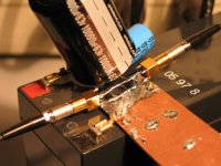
The cabel. Obviously I don't have here that as well. You suggest
RG223, which is a 50 ohm silver plated Cu coax, 5 mm diam, 100 pF/meter self capacitance.
Now I have here a 50 ohm coax, 5mm diam, [not 6.3], measured capacity / 1m is 100 pF. It is tinned Cu, alu foil, so not the same, but may I say, electrically close?
I will use 1m of it in the setup.
The SLA. Now we arrived to the hot point. You can guess, that it was not without reason that I did not put it yet on the network analyzer, and used a far from real simple short in my previous set in place of it. I did that, because I wanted to emphasise, that even without the battery, that is, with an ideal bypass impedance instead, the cable inductance itself will cause problems.
But this was not the real reason.
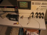
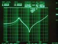
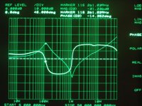
The analyzer.
Although it's written on it, that you can not put more then 28 dBm or 30V dc on it's ports, would you be willingly challenge HP for it?
I did it now, out of respect for You, [and curiousity], so as to get some idea about the real thing.
This was not a smooth ride, and there was a moment, with all alarms ON and nothing working, that I was facing .. well, lets forget about it. You all ove me a capuccino!
But, I quickly saved that result, and then made up a simple DC - decoupler jig, and repeated the measurement, in the hope that the battery self inductance will be greater, than that of the jig.
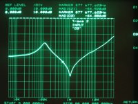
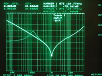
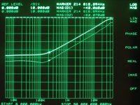
I have only one such an SLA, 12V 7Ah Fiamm model. So this will be used, and you will have to move the resonace peak by sqroot 2, if you want to deduct the 24 volt case.
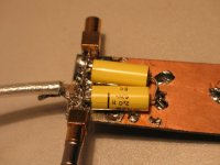
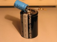
Here is the capacitor, that I came up with: 4 uF, and I swear You that it had a self resonance, at the beginning, at 1.137 MHz.
Now it had shifted down a bit, as you will see.
I did not have the time to reply to You during the day, excuse me.
Thank's for the fast reaction!
You are right, I was not exactly following your suggestions, but you have to admit that there remained some particulars still to clarify?
And now, let's get to the job.
Please take an Epcos Cap and a piece of RG223 Cable and bridge at the end using a workable model of an SLA combo of 2 X 12V/12AH in series. That will look rather different I should think.
Modelling the battery as 0.001R/1uH and including 1m heavyish duty 50R CI coax cable as lumped 0.15R/250nH/100pF (including contatct resistance) my bypass suggests a resonance at around 65KHz with a peak impedance of a little over 1R, snubbers show little/no effect on Z, Phase otation of current vs. voltage looks to be no more than +80/-60 degrees.
So, I would like to resume, what I understood up to now:
The cap. Epcos B32560, 4,7 uF 40 or 63 volt? which is an MKT type.
You seemed to agree with Peranders in that it has self resonance dip at ~ 1.2 MHz.
Now, would you let me to try & make up a sostitute for it, with similar electrical parameters? Maybe we can agree to repeat the measurements later, if I eventually get one. The influence of this on the measurements will be the series resonace frequency following strictly the cap parameters, can we agree on this?
The cabel. Obviously I don't have here that as well. You suggest
RG223, which is a 50 ohm silver plated Cu coax, 5 mm diam, 100 pF/meter self capacitance.
Now I have here a 50 ohm coax, 5mm diam, [not 6.3], measured capacity / 1m is 100 pF. It is tinned Cu, alu foil, so not the same, but may I say, electrically close?
I will use 1m of it in the setup.
The SLA. Now we arrived to the hot point. You can guess, that it was not without reason that I did not put it yet on the network analyzer, and used a far from real simple short in my previous set in place of it. I did that, because I wanted to emphasise, that even without the battery, that is, with an ideal bypass impedance instead, the cable inductance itself will cause problems.
But this was not the real reason.
The analyzer.
Although it's written on it, that you can not put more then 28 dBm or 30V dc on it's ports, would you be willingly challenge HP for it?
I did it now, out of respect for You, [and curiousity], so as to get some idea about the real thing.
This was not a smooth ride, and there was a moment, with all alarms ON and nothing working, that I was facing .. well, lets forget about it. You all ove me a capuccino!
But, I quickly saved that result, and then made up a simple DC - decoupler jig, and repeated the measurement, in the hope that the battery self inductance will be greater, than that of the jig.
I have only one such an SLA, 12V 7Ah Fiamm model. So this will be used, and you will have to move the resonace peak by sqroot 2, if you want to deduct the 24 volt case.
Here is the capacitor, that I came up with: 4 uF, and I swear You that it had a self resonance, at the beginning, at 1.137 MHz.
Now it had shifted down a bit, as you will see.
Attachments
XELB said:I don't know what kind of speakers you have ,but, I can only take all the "juice" from my speakers when I use amplifiers with big capacity. (like 40,000nF, 300VA transformer)
(I Know it depends on the type of music, cables you use, etc...)
I always say capacitance per rail.
So, when I recommend between 10,000uf to 20,000uf it is per rail.
It it more than enough for these amps, and I have difficult speakers.
And you should stop confusing nF (nanofarads) with uF (microfarads).

XELB said:But why should be diferent with this kind of amplifiers ?
Each case is a case.
And these are not class-A amps.
carlosfm said:
I always say capacitance per rail.
So, when I recommend between 10,000uf to 20,000uf it is per rail.
It it more than enough for these amps, and I have difficult speakers.
And you should stop confusing nF (nanofarads) with uF (microfarads).
Each case is a case.
And these are not class-A amps.
OK! I thought it was "total" capacitance!
In that case that's the ideal for me 😀
40,000uF / 2 = 20,000 nF

And like you, I share the opinion that between 10,000uf to 20,000uf is enough.
Have you tried in speakers with more than one driver ?
Normally they are hard to drive.
Thanks, next time I will not mistake the "miu"(u) with the n(nano)

- Status
- Not open for further replies.
- Home
- Amplifiers
- Chip Amps
- Carlos' snubberized Gainclone Power supply