steenoe said:Hmmmm, this one I do not buy: In fact, I feel strongly, that is all, this is about!
It is so very easy to try the idea of CarlosFM. Actually I searched the web on PSU building. All my findings pointed to CarlosFM's ideas! I will not claim that he invented it, but he did bring the facts to our attention. No doubt, whatsoever about that🙂
I have build several chipamps, and none of them was as good as those with CarlosFM's "snupper'd" PSU's. Very tight bass, in comparison to a generic chipamp. I really didn't like chipamps until I listened to this one. (See pic). I made 2 of those for a friend.
He is very happy about it🙂
Sorry, you don't get my point. I just answered Jeff, please read that post above this one, no use taking up bandwidth to repeat myself.
Jan Didden
Kuei Yang Wang said:Konnichiwa,
Correct, it is not Witchhunting, as a Witch is of Female gender, I suspect we would have to call it warlock hunting.
Finally we have reached the crux of the matter.
The issues are actually much deeper and there is a VERY VESTED interest from the Pseudo Objectivists. What vested interest you ask?
They have a larger part of their life invested into a particular worldview. In this worldview Cables make no audible difference, RC snubbers make no difference and the list goes on endlessly. And anyone having experiences to the contrary "is in on it". Anyone disagreeing is either deluded by "those multi-kilo dollar cable peddlers, brilliant pebbles, magic pens," or "makes a killing".
The problem with this worldview is that it absoltely cannot tolerate ANY invalidation in however samll a matter (such as the issues around PSU Line impedance & resonances that overtly are the topic here).
Because if such an overall, ironcast, rigid view is wrong in the least, it would require a full re-evaluation of what the individual has accepted ex cathedra, usually without any material evidence as dogmatic article of faith. Instead a regular, rigid and liberal application of doublethink and duckspeak is made.
So, we must forgive these poor deluded souls, after all, they only defend the orthodoxy of their particular religion, which also requires to burn warlocks at the stake and oppose, shariat like anything it dislikes, even in those who do not subscribe to the same religion....
As they man said when they nailed him to some wood, "...fro they do not know...". So we may happily forgive and forget. I'm sure they feel all better now given that the REAL reasons have finally been brought to light again.
Sayonara
Hi Thorsten,
Nice story, but has nothing to do with my worldview. You also didn't get my point. I never said cables make no difference, I never said snubbers make no difference. Why do you continue to read in other people's posts things they never said? May I be so bold to ask you to read my above answer to Jeff, not to take up etc.?
Jan Didden
carlosfm said:[snip]EDIT: Jan, I see... you didn't get it.
I'm going to quote myself and insert two new words, to make it clear:
Originally posted by carlosfm
I arrived to this schematic in a couple of hours testing and listening.
In my mind, I had previously the feeling that this PSU approach was the way to go. It was.
Clear?
Carlos,
My point is, and was, that because your mind was set up, you could only reach the conclusion you did reach, whatever the effect of your changes.
Jan Didden
motherone said:[snip]It'd also be nice to see some test results from a scope on both the PSU and the amp output with no PSU zobel, with carlos's values, and maybe with the optimized values.
Who knows, maybe I'm an idiot smoking crack here, but maybe what I posted here makes sense to someone 😀
You make sense to me.
Jan Didden
CarlosFM,
On your regulated version, I think you ended up on the regulated with a 33uF cap at the amp chip after stopping there after reducing the size. I think you said it was a Philips cap of some sort. I believe you did not bypass this cap.
I will probably try that and the .47uF.
This discussion makes me think that something interesting I might try on the regulated (when I get my RIGC together enough - a few minutes of slow but steady progress every day!) will be a higher value cap such as 100-200uF but use a very low impedance series such as the Nichicon HE series (UHE). The idea would be to get increased "reservoir” near the chip but reduce the impedance below what the .33uF likely is.
If you did not find much benefit (I don't remember if it was discussed?) from bypassing the 33uF then perhaps the level of impedence on the 100-33uf is small enough anyway and the difference was really the reduction in capacitance. Still the low impedence 47uf-200uF cap seems interesting to try.
demogorgon said:[snip]Jannemann: would you like some cheese to go with that WHINE? 😀
(just couldn't resist..)
Huh? Her name was Jenny...
Jan Didden
Konnichiwa,
Who then wrote:
"That is exactly the way those multi-kilo dollar cable peddlers, brilliant pebbles, magic pens, whatever, etc make their killing. They insinuate that if you can't hear the enormous improvement with their stuff, you're one of these suckers with wooden ears. And who wants to be that, right?"
That was written clearly by someone who believes strongly that anyone who hears differences from "multi-kilo dollar cable, brilliant pebbles, magic pens, whatever, etc " is deluded, which inherently implies that there is no audible difference to start with.
Who wrote:
"- Audibility means that the movement of the speaker cone(s) changes so much in the middle of the complex movements resulting from the music reproduction that the change is audible;
- Thorsten's simulations show that the impedance of a power supply changes to a lower value upwards of 250kHz with those snubber things;
- Carlosfm maintains he can hear the differences introduced by those supply changes."
Again, while not saying directly "there is no audible difference" you imply there cannot be one such, as anything in the powersupplies at 250KHz could not possibly cause something to be audible with music.
You may not say "X is reliably inaudible" but what you write is aimed at insunating that it is and that anyone who nevertheless hears any difference is a deluded fool and/or Suckered Sucker...
Sayonara
janneman said:Nice story, but has nothing to do with my worldview.
janneman said:I never said cables make no difference, I never said snubbers make no difference.
Who then wrote:
"That is exactly the way those multi-kilo dollar cable peddlers, brilliant pebbles, magic pens, whatever, etc make their killing. They insinuate that if you can't hear the enormous improvement with their stuff, you're one of these suckers with wooden ears. And who wants to be that, right?"
That was written clearly by someone who believes strongly that anyone who hears differences from "multi-kilo dollar cable, brilliant pebbles, magic pens, whatever, etc " is deluded, which inherently implies that there is no audible difference to start with.
Who wrote:
"- Audibility means that the movement of the speaker cone(s) changes so much in the middle of the complex movements resulting from the music reproduction that the change is audible;
- Thorsten's simulations show that the impedance of a power supply changes to a lower value upwards of 250kHz with those snubber things;
- Carlosfm maintains he can hear the differences introduced by those supply changes."
Again, while not saying directly "there is no audible difference" you imply there cannot be one such, as anything in the powersupplies at 250KHz could not possibly cause something to be audible with music.
You may not say "X is reliably inaudible" but what you write is aimed at insunating that it is and that anyone who nevertheless hears any difference is a deluded fool and/or Suckered Sucker...
Sayonara
moving_electron said:CarlosFM,
On your regulated version, I think you ended up on the regulated with a 33uF cap at the amp chip after stopping there after reducing the size. I think you said it was a Philips cap of some sort. I believe you did not bypass this cap.
I will probably try that and the .47uF.
Correction. I meant 47uF.

janneman said:I understand what you are saying, but I didn't say there can be no difference. I have made my ideas clear a zillion times, but I understand that a single post in isolation is just that. My strong feelings are that a simple, sighted listening test by someone who is obviously involved in the results (like the guy who made the mod in the first place) is totally unreliable. I don't care whether his results or reports happen to be in line with what I think it should be or not. The result, in this discussion, is irrelevant. The point is that the result is totally unreliable. It is unreliable for the party reading it as well as for the party reporting it.
Jan Didden
Jan, please...
I'd like to taste some of your wine.😀
You have something with listening tests, or is it your ears that are unreliable?
I told you: high capacitance sounded very bad to me, as much as I wanted it to sound good.
As much as I wanted, Dejan's recommendation of 1R + 560nf didn't sound good to me.
Am I biased to 1R + 100nf? Why? Can you explain?
Is this all in my head?
Are we all deaf?
The ones who tried it after me?
Am I such an inexperienced listener that I let myself fool so easily?
You don't know me.
Even then, I'd like to know you. I don't know why, but I respect you.🙄
Upupa Epops said:To Carlos : Look at my schematic - there is one thing, which you don't have in your PS. Try to think why is there.
I'm looking, and here's what I see:
1. Single bridge, for CT trafo.
2. 15~22,000uf 35~40v (strange for who recommends a "DC supply range from ± 20V DC to± 40V DC").
3. 3.15AF fuse (these won't allow parties, and forget 4 ohm speakers😀 )
4. 220 nf/100v caps
5. 100uf/100v + 1uf/63v caps
So... am I missing something here?
This is not enough to make the amp sound decent with these big caps.
janneman said:My strong feelings are that a simple, sighted listening test by someone who is obviously involved in the results (like the guy who made the mod in the first place) is totally unreliable.
How then can a DIYer ever make reliable judgements? A blind test doesn't change the fact that you are involved in the results.
Do you hire uninvolved strangers to select the gear in your system?
High, I am new to this forum, so please, be patient with me...
I just thought to join in to add some measurement results, which might
clarify the picture a bit better.
I really enjoyed Thorsten"s analysis, and I think, in these relatively simple situations the results can be good. Given the fact that I can have access to an old but good HP network analyzer, I tried to put together a small and simple test setup. (Actually, I have done similar tests already before, so I just used the same jig again)
So, the setup is:
I am using the HP network analyzer S-parameter test setup, and measuring S21, that is, the forward transmission coefficient.
I have two measurement ports: in case of S21, the Port 1 puts out a swept sinus signal with 50 ohm characteristic impedance, and on
Port 2, with 50 termination, the signal amplitude and phase is measured.
If one connects Port 1 to Port2 with a 50 ohm coax, on the screen there will appear a 0 dB attenuated straight line for the full bandwith tested. In this case, I chose 5kHz - 100MHz.
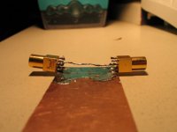
The test jig consist of two Lemo 50 ohm female connectors facing each other, soldered to a ground plane. A wire closes the circuit for signal "hot". That is, I am creating a breakout for the coax, so I can short the signal "hot" to ground, trying to attenuate it. Because
we have 50 char. impedance, in our case a 5 ohm short to ground will mean .. -14dB! (because, looking at the test point, it originally had 25 ohm impedance to ground..)
For a better catch, I'm including the pic of the test jig:
I just thought to join in to add some measurement results, which might
clarify the picture a bit better.
I really enjoyed Thorsten"s analysis, and I think, in these relatively simple situations the results can be good. Given the fact that I can have access to an old but good HP network analyzer, I tried to put together a small and simple test setup. (Actually, I have done similar tests already before, so I just used the same jig again)
So, the setup is:
I am using the HP network analyzer S-parameter test setup, and measuring S21, that is, the forward transmission coefficient.
I have two measurement ports: in case of S21, the Port 1 puts out a swept sinus signal with 50 ohm characteristic impedance, and on
Port 2, with 50 termination, the signal amplitude and phase is measured.
If one connects Port 1 to Port2 with a 50 ohm coax, on the screen there will appear a 0 dB attenuated straight line for the full bandwith tested. In this case, I chose 5kHz - 100MHz.
The test jig consist of two Lemo 50 ohm female connectors facing each other, soldered to a ground plane. A wire closes the circuit for signal "hot". That is, I am creating a breakout for the coax, so I can short the signal "hot" to ground, trying to attenuate it. Because
we have 50 char. impedance, in our case a 5 ohm short to ground will mean .. -14dB! (because, looking at the test point, it originally had 25 ohm impedance to ground..)
For a better catch, I'm including the pic of the test jig:
Attachments
ok, so I will try to continue with my results:
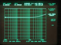
here is a pic of the calibration of the test jig - I've put 1 ohm to the ground, and this is the result on the screen:
Like in the example (5 ohm ) before, with reference to the original net impedance of 25 ohm, now we have - 28 dB attenuation.
The impedance is flat up to cca 30 Mhz, then starts to be inductive - no wonder, with such a simple jig..
Attachments
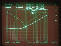
And now, lets start with the real thing!
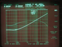
Thorsten was talking about cheap bad Jamicons, so let us have a look at a cheap bad Jamicon 10000 uF, 63v. (it's really big..)
There are two signal traces: magnitude of the attenuation, and the phase. ESR is ~ 20 mOhm, not so bad.
Given the fact, that we have a 3 dB corner frequency of ~ 130 - 140 kHz, with respect to the 20 mOhm Esr, the equivalent ESL seems to be around 24 nH. This coincides nicely with the findings of Jacka Racman.
Sorry, Thorsten!
Attachments
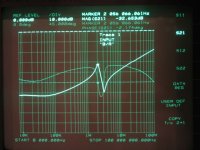
here it is the previous arrangement, but now with a 680nF + 1ohm
added. sorry, I just can't call it "snubber"!
What is possible to see, is that it has not changed too much.
But! Don't forget, that up to now we measured an impossible bypass arrangement - 10000 uF directly on the pins!
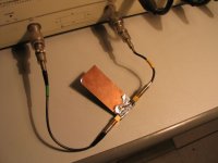
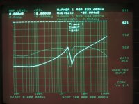
What would happen, if we turn back to the real world, and have not much, lets say 2 inches of distance for the big cap from the pins, and the Wima right on the pins?
added. sorry, I just can't call it "snubber"!
What is possible to see, is that it has not changed too much.
But! Don't forget, that up to now we measured an impossible bypass arrangement - 10000 uF directly on the pins!
What would happen, if we turn back to the real world, and have not much, lets say 2 inches of distance for the big cap from the pins, and the Wima right on the pins?
Attachments
- Status
- Not open for further replies.
- Home
- Amplifiers
- Chip Amps
- Carlos' snubberized Gainclone Power supply