Did you install 18v Zeners instead of 15v?
When installed, did the two zeners read their rated voltage when measuring the voltage directly across them?
Does the Zener now read shorted?
What was the part number of the Zener you installed?
When installed, did the two zeners read their rated voltage when measuring the voltage directly across them?
Does the Zener now read shorted?
What was the part number of the Zener you installed?
No, it was 15v Zeners.Did you install 18v Zeners instead of 15v?
yes but those voltage was 18V.When installed, did the two zeners read their rated voltage when measuring the voltage directly across them?
Does the Zener now read shorted?
Are you saying that, after the 15v Zener was installed, you read 18v across it?
Is the jumper shorting to pin 1 of the op-amp?
Are you saying that, after the 15v Zener was installed, you read 18v across it?
Is the jumper shorting to pin 1 of the op-amp?
Yes.Are you saying that, after the 15v Zener was installed, you read 18v across it?
I think jumper is fine and not interfering with any ICs because it was worked perfectly when my amp was not shorted.Is the jumper shorting to pin 1 of the op-amp?
You 'think' the jumper is fine?
^^ Why not confirm?
Remove the op-amp that was heating up.
Remove the shorted Zener but don't power up the amp without it.
You stated that both large resistors were 150 ohms. Do you read 150 ohms across each one while in the board?
Has the rail voltage changed from ±18v?
What was the 12v supply voltage when you read ±18v of rail voltage?
Please answer all questions.
i already remove it. Please tell if op-amp's vcc+ and vcc- give beep in continuity mode then what its mean.Remove the op-amp that was heating up.
Bro, I found the same video on YouTube which happened to me but it is in Hindi but you can use subtitles.
I don't watch repair videos. If it's the same, did it solve your problem?
If not, please answer the questions I posted.
If not, please answer the questions I posted.
Bro I have answered your question please seeIf not, please answer the questions I posted.
You stated that both large resistors were 150 ohms. Do you read 150 ohms across each one while in the board?
Has the rail voltage changed from ±18v?
What was the 12v supply voltage when you read ±18v of rail voltage?
If it's the same, did it solve your problem?
Has the rail voltage changed from ±18v?
What was the 12v supply voltage when you read ±18v of rail voltage?
If it's the same, did it solve your problem?
Thank you brother. My amp is working now and the problem was in the two TL074CN op-amp ICs.
I can't find these op-amps near me but I will replace them soon but after removing them temporarily the rest of the channels are working now.
This wouldn't have been possible without your help, you taught me a lot about amps. Thank you.
I can't find these op-amps near me but I will replace them soon but after removing them temporarily the rest of the channels are working now.
This wouldn't have been possible without your help, you taught me a lot about amps. Thank you.
Hlo,
I replaced the old OP-AMPS but now the Channels Transistors of left side getting hot when speaker is connected.
I replaced the old OP-AMPS but now the Channels Transistors of left side getting hot when speaker is connected.
If you measure directly across the two speaker terminals of each channel, what is the greatest DC voltage you read on any channel?
In the left channel which is not working it shows 0.70 V and in the right channel which is working it shows 0 V.If you measure directly across the two speaker terminals of each channel, what is the greatest DC voltage you read on any channel?
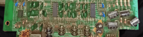
Have you removed 100% of the brown fixative that's been applied to some of the various components?
What's the DC voltage on all of the output terminals of the op-amps you replaced?
What's the DC voltage on all of the output terminals of the op-amps you replaced?
Yes.Have you removed 100% of the brown fixative that's been applied to some of the various components?
30V In the right side and 0.25V in the Middle one and 0.25V in the left side's small op-amp.What's the DC voltage on all of the output terminals of the op-amps you replaced?
Attachments
There are 4 output pins per each 14 pin op-amp. You need to post the pin number and the voltage.
Is that an old photo? I see the fixative on some components.
Is that an old photo? I see the fixative on some components.
- Home
- General Interest
- Car Audio
- Car Amplifier have power but no sound. Please help me