How many turns around the ferrite you use depends on what frequency range you are trying to exclude. More turns means more inductance/loss (and hence the attenuation goes lower in frequency) but also more stray capacitance (so the upper frequency for attenuation gets lower).
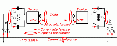
Inphase transformer currents does not weaken the signal, but reduces the interference currents. Inphase transformer useful in any place of the loop interference of the oval.When the two opposite direction currents are identical, then there is no effect from the ferrite.
Attachments
You're right. But, usually, this transformer contains too few turns in order to worry about their capacity. This capacity may only become apparent at very high frequencies.How many turns around the ferrite you use depends on what frequency range you are trying to exclude. More turns means more inductance/loss (and hence the attenuation goes lower in frequency) but also more stray capacitance (so the upper frequency for attenuation gets lower).
T117, Thanks for joining the conversation. I measured my amplifier a couple of months ago and the measurements look fine. Below was a shot of the image when the amplifier was loaded with 8R and injected 10kHz square waves.
Do the square waves look fine? I guess so. Did the amp sound good? Definitely not. So I followed this thread's advice and reduced some LRs and added more C to the PSU. Each time I added more C, the amplifier sounded better. But I bet if I measured the amp again, the graph of 10k square waves would still pretty much look the same. If I need to find out the real differences, I would probably need to really study EE and get some fancy expensive equipment before I would even dare to try it.
I wouldn't use 10KHz waveforms to analyze for projected bass sound changes. Use 20 Hz @4 ohms and look for sagging rails, ripple etc.
Match the testing for the types improvements youre wanting to analyze.
Square wave testing measure the rise and fall times and look for overshoot etc.
take care testing at high power on continuous waveforms this is serious amp stress.
No that's an excuse , its possible with common sense & lots of research, your tools if not the serious ones can cause errors, this requires more knowledge to interpret the results. Common sense goes a long way indeed. which means solve the big problems 1st, before you go down a rabbit hole.If I need to find out the real differences, I would probably need to really study EE and get some fancy expensive equipment before I would even dare to try it
Last edited:
If you have tried using clamp-on ferrites when dealing with MHz signals on the bench, then you know that sometimes they help, sometimes they just make things worse. It all depends on where you put them and what kind of ferrite. If they're not lossy at just the right frequency, they just become resonators.
If you want to put a ferrite somewhere, think of what impedance will be in parallel with it, and what kind of characteristics it would need to have to not just become another antenna.
If you want to put a ferrite somewhere, think of what impedance will be in parallel with it, and what kind of characteristics it would need to have to not just become another antenna.
If you have tried using clamp-on ferrites when dealing with MHz signals on the bench, then you know that sometimes they help, sometimes they just make things worse. It all depends on where you put them and what kind of ferrite. If they're not lossy at just the right frequency, they just become resonators.
The clamp-on ferrites are problematic in that the ferrites are supplied with some of the lowest grades of materials and they don't work unless the mating surface is perfectly aligned and clean, microscopically clean with lint free swabs etc. I'd order a bunch of High Mu toroids that can accept the mains/speaker connector thru the center and wind 5-15 turns. edit> note If you're new to using ferrites on audio you'd be advised to stick to CM chokes...
I have never seen simple CM chokes make things worse. They've helped many antennas (see "Balun") In fact sometimes I use them on O-scope x1 probe leads esp. looking at SMPS noise.
can you clarify, this is about CM chokes?If you want to put a ferrite somewhere, think of what impedance will be in parallel with it, and what kind of characteristics it would need to have to not just become another antenna.
Last edited:
It can apply to clamp on ferrites (a specific form of CMC) as well as CMCs, or any inductor anywhere really.
I had not thought about the clamp on surface mating. I have noticed while watching with my scope that most of the ferrite's effect kicks in as the toroid halves are mating, which makes sense. I had to shim the insides of the plastic case in order to keep them pressed against each other, although they seemed to work fine before.
When I've used CM chokes I tend to use them for 100KHz stuff, although I have used small ones for probing and signal injection purposes. Most recently I found using the invert+add function on my Tek scope worked better than the ferrites.
Thanks, guys. From now on I will be careful with clamp on ferrites.
Would ferrite beads have the same problem?
Also, I have just found some ferrite beads with 4 leads. Are those 4-lead ferrite beads for common mode noise suppression? Can they be used for signal?
Would ferrite beads have the same problem?
Also, I have just found some ferrite beads with 4 leads. Are those 4-lead ferrite beads for common mode noise suppression? Can they be used for signal?
Last edited:
The clamp-on ferrites are problematic in that the ferrites are supplied with some of the lowest grades of materials and they don't work unless the mating surface is perfectly aligned and clean, microscopically clean with lint free swabs etc. <snip>
Whoa cowboy!
"Supplied with some of the lowest grades of materials"??
I think that depends entirely on where you source the ferrites.
There are very high quality suppliers of "clamp on" chokes.
What's this about mating surfaces?
News to me...
Try this to getcher feet wet:
audiosystemsgroup.com/RFI-Ham.pdf
the same fellow has a lot of other good advice on things that go audio and HF together...
many tests of ferrite materials in one pdf here:
K9YC Publications
many tests of ferrite materials in one pdf here:
K9YC Publications
practice with all kinds of ferrite core halves, the inductance tends to vary with lots of things. clamping pressure & cleaning the mating surface is a biggy. Wiping each surface w/ heavy stock paper works well.
I should of said not the highest quality materials are in , no name clamp-ons. why is this a surprise? many are sold on Amazon / big box stores with few claims so....
I tend to buy raw stock from magnetics distributors... no ready mades
I should of said not the highest quality materials are in , no name clamp-ons. why is this a surprise? many are sold on Amazon / big box stores with few claims so....
I tend to buy raw stock from magnetics distributors... no ready mades
yes, cheap is cheap... you did not originally limit the potential range of products.
What sort of variations are you seeing at what frequencies, with what core material, and what wire? Curious about your report.
What sort of variations are you seeing at what frequencies, with what core material, and what wire? Curious about your report.
had a production issue a couple of times on flyback transformers. Cleaning and glue core halves solves it. schmutz / dirt creates a gap at the mating surface. cores were right from the factory Styrofoam packing.Curious about your report.
Last edited:
Hi, I want to borrow this space to learn a thing from you.
For connecting 6 ore more large size screw terminal type reservoir caps (H:80mm x D:50mm), the typical way is to use aluminium / copper bars.
Can I use 1.6mm thick 2 layer 2 oz FR4 PCB (made to the same size and width as the aluminium / copper bars) instead?
PCBs are very cheap these days. This saves cutting and drilling holes, etc, and saves a lot of time.
I think resistance is not an issue. The issue may be that the FR4 boards may be too soft so the screw contacts may become loose one day. But then I can tighten them up again, can't I? What do you think?
On Computer Grade Caps use internal tooth washers on screws/ shouldn't be any other issues with using 2 oz. Use plated thru clearance holes to join top and bottoms.
supporting the caps might be an issue.
supporting the caps might be an issue.
On Computer Grade Caps use internal tooth washers on screws/ shouldn't be any other issues with using 2 oz. Use plated thru clearance holes to join top and bottoms.
supporting the caps might be an issue.
Thanks. Since you gave it a tick I feel safe to do it that way.
Can the caps site up-side-down on the chassis? i.e. the screw terminals with PCB "bars" on the top side, and the other sides of the caps touch the bottom of the chassis.
Would the capacitance of up to a few hundred pF formed between the aluminium shells and the chassis cause problem? I guess it shouldn't be because the power supply ground is connected to the chassis anyway.
Last edited:

Personally, I would not apply a lockwasher to the surface of a PCB. First, I would coat the area with amount around the hole of solder, as thick as possible. If necessary you can use a file to make the surface flat.
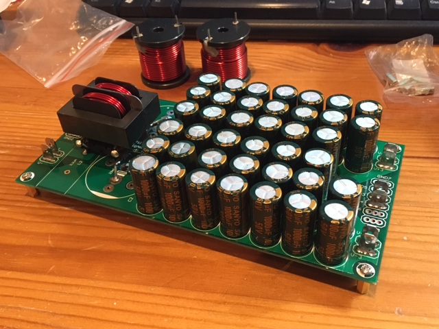
Qnty 40 x Sanyo 1000uF 50v caps is cheaper than two 22,000uF caps and lower ESR.
Good stuff.
I have got a lot of big caps already so I use a mix of both. So far there are no problems. I would get the small cap array directly on the same board as the output device or get them very close.
- Status
- Not open for further replies.
- Home
- Amplifiers
- Solid State
- Capacitor Array on Power and Ground planes – How to Avoid Resonance?