Why should this be? How good can you hear at 20 kHz or 100kHz or 1MHz?I guess I expressed it incorrectly. I actually thought that low impedance at higher frequencies was more important, and less important at lower frequencies, hence the CLRCLRCLRC design, which attenuates RF much better but increases DC impedance and keeps RF impedance the same. This is in considerations of amplifier's PSRR getting worse and worse towards higher frequencies.
And where should the RF signal come from?
The impedance has not much to do with this. It's the ripple of your power supply voltage.
The peak of your hearing sensitivity is about 500Hz - 2kHz.
Ripple is mainly due to Power Supply: 100 (120Hz) + some harmonics,
therefore Power Supply Rejection Ratio is important at 100Hz-500Hz.
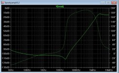
Using the LTSpice modelling I have obtained the amplifier's PSRR figures.
For the IPS and VAS combined, PSRR has the following figures:
20Hz -> -69dB
50Hz -> -69dB
100Hz -> -69dB
200Hz -> -68dB
500Hz -> -64dB
1,000Hz -> -59dB
2,000Hz -> -53dB
5,000Hz -> -46dB
10,000Hz -> -40dB
20,000Hz -> -34dB
50,000Hz -> -26dB
100,000Hz -> -20dB
For OPS, PSRR has the following figures:
20Hz -> -131dB
50Hz -> -122dB
100Hz -> -116dB
200Hz -> -111dB
500Hz -> -103dB
1,000Hz -> -96dB
2,000Hz -> -91dB
5,000Hz -> -83dB
10,000Hz -> -76dB
20,000Hz -> -70dB
50,000Hz -> -63dB
100,000Hz -> -57dB
Because the IPS and VAS stages have much poorer PSRR, I am employing a capacitor multiplier with low output impedance to help. The OPS stage has good PSRR at low frequencies (so the increase of the PSU impedance due to CLRCLRCLRC does not matter) but it gets poorer at higher frequencies.
Subjectively, after I completed the first build, I experimented changing various big reservoir caps, and found that the lower the impedance of the caps, and the larger values of the caps, provided the better sound. How? I suspect that ripples are reduced and RF filtering is better and PSU impedance is lower.
This looks wrong. You need to simulate the complete amplifier with feedback.
Then you need to have a look at your power supply ripple. Bye a cheap oscilloscope.
The simple VAS type amplifier has a PSRR problem. A simple R-C Filter (100R-330uF) for the small signal stages or a better topology will help to solve this problem.
Let me know if you find any obvious errors in layout, wiring, etc.
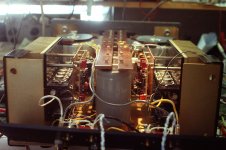
This is my second attempt to build the amp. For the time being it sounds worse than its previous build that seemed to violate all the good design principles. A photo of the first build is attached below.
I don't know what I have done wrong.
Your previous build was better , in my opinion.
You are wrong for analog audio "design principles". All them planes and
"dc to light" has diminishing returns. Better to design for minimum loop area
at the main amp decoupling and concern yourself with <100Khz amp PSRR.
It looks like your amp design is a symmetric "leach type" topology. -90db
and >-100db (at 10-20k)PSRR with cap multipliers (below).
So , you have excellent rejection over the audio band and usable rejection
right up to >1mhz.
Anything above that would would exceed the amps bandwidth , that same
amp has negative closed loop gain >1mhz.
You are designing for something that should not exist (in audio).
OS
Attachments
Last edited:
I have done simple measurements of the amplifier with 8R resistive load. The results look fine. But the amplifier doesn't sound as good as before. It sounds harsher.
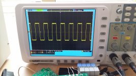
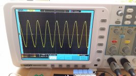
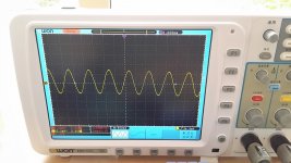
Below are 3 photos showing 10kHz square waves, 100kHz sine waves and 1MHz sine waves when the amplifier has a 8R resistor load.
Below are 3 photos showing 10kHz square waves, 100kHz sine waves and 1MHz sine waves when the amplifier has a 8R resistor load.
Attachments
Ok, then switch off the generator and measure the output signal. It should be very small.
If you cannot measure it, use speakers or headphones to listen to it.
Ideal you should not see or hear anything.
Then look at your power supply with a 4 Ohm load.
How much ripple do you measure?
How much ripple do you measure when you turn on the amplifier (use a 20Hz Sinus or Rectangular signal).
If you cannot measure it, use speakers or headphones to listen to it.
Ideal you should not see or hear anything.
Then look at your power supply with a 4 Ohm load.
How much ripple do you measure?
How much ripple do you measure when you turn on the amplifier (use a 20Hz Sinus or Rectangular signal).
Your previous build was better , in my opinion.
You are wrong for analog audio "design principles". All them planes and
"dc to light" has diminishing returns. Better to design for minimum loop area
at the main amp decoupling and concern yourself with <100Khz amp PSRR.
It looks like your amp design is a symmetric "leach type" topology. -90db
and >-110db (at 10-20k)PSRR with cap multipliers (below).
So , you have excellent rejection over the audio band and usable rejection
right up to >1mhz.
Anything above that would would exceed the amps bandwidth , that same
amp has negative closed loop gain >1mhz.
You are designing for something that should not exist (in audio).
OS
Thanks. You are right that my amp topology is very similar to the Leach amp.
Well, other than the capacitor multiplier area, I thought I had kept the current loops small, and much smaller than the first build. I use a lot of copper areas for the ground to reduce the magnetic fields.
Based on that PCB, could you point out the wrong designs please?
In terms of bandwidth beyond 1mHz, theoretically I agree with you. In reality, I have tried using commercial Corcom mains filters and found them improve sound. I have had many audio friends who did "blind tests" to pick a set up with or without the mains filters. All active equipment from CD player to preamp to power amp were powered with or without the mains filters. The result was quite consistent. With the mains filters, the sound was a bit clearer.
(Scotland Yard detective) Gregory: "Is there any other point to which you would wish to draw my attention?"
Holmes: "To the curious incident of the dog in the night-time."
Gregory: "The dog did nothing in the night-time."
Holmes: "That was the curious incident."
In this case dog="pulse" . The curious incident is the fact that the Wurth datasheet for the 21A (DC), 52A (saturation) inductor does not mention the word "pulse" at all. Ne'er even once. The strategem is to employ an obscure phrase like "Silver Blaze" in the hope that its incongruity will impel the reader to actually open the datasheet .pdf file and scan for the word "pulse". It worked by the way.
The cap multipliers are a real good addition , without them the Leach
would just have "good" PSRR.
I've seen/ repaired thousand's of units , very few use "embellished" PS's.
Some even use very cheap supplies. The 70's Sansui is notorious for
"el cheapo" PS's. By using this topology .... I see what they did.
The amp has clearly the best < 500 hz rejection (below).
So , they saved money on caps using the amp as "cleanup".
PS- builders have liked the Sansui more than the Leach. I have the
Leach now and have not built a Sansui yet 😱 .
Native PSRR seems to be the bigger "wow" factor for amp SQ.
OS
Attachments

If you spend a lot of time concentrating on things which are unimportant then you will have less time to spend on things that matter such as grounding. In addition, reducing ripple to infinitesimal proportions by passive means will almost inevitably mean a highish subsonic and DC output impedance. This creates a feedback path, and can cause motorboating. A good PSU has a lowish output impedance at all frequencies of interest. For an audio amplifier PSU you should be interested in DC to perhaps 100kHz; above that you should rely on local decoupling.HiFiNutNut said:Thanks. If you could please elaborate a bit more.
You guys have a good point.
DF, I thought that the mains impedance and the transformer have produced 0.5 to 0.7R resistance. Having a CLRCLRCLRC PSU with the values of R I use only doubles the impedance up. i.e. 6dB. Is this 6dB sufficient to cause the problem you described?
DF, I thought that the mains impedance and the transformer have produced 0.5 to 0.7R resistance. Having a CLRCLRCLRC PSU with the values of R I use only doubles the impedance up. i.e. 6dB. Is this 6dB sufficient to cause the problem you described?
I think one thing I can try is to short all R and L in the PSU board. This will lower the PSU impedance and help me to find out if the power and ground plane capacitance was the problem, as in that case the problem would be multiplied.
It looks like that the common concensus is to have a low PSU impedance up to 100kHz.
I previously found in Spice simulation when probing the current of the active devices a lot of sharp edges right up to the MHz region. For that reason I was targeting low supply impedance up higher and came up with the idea of cap array on power and ground planes. Perhaps those sharp edges are not as bad as they appear in simulation?
I previously found in Spice simulation when probing the current of the active devices a lot of sharp edges right up to the MHz region. For that reason I was targeting low supply impedance up higher and came up with the idea of cap array on power and ground planes. Perhaps those sharp edges are not as bad as they appear in simulation?
The DC impedance of a PSU is not found by simply adding up the resistances on the AC side and the DC side. The AC resistances are only connected for a fraction of the AC cycle so this effectively multiplies them. Another way of looking at it is to calculate the droop in voltage across the reservoir cap during the time it is not being charged, halve it and divide by the DC current draw. This gives the effective DC resistance of the rectifier plus cap. Then add on the other DC resistances.HiFiNutNut said:DF, I thought that the mains impedance and the transformer have produced 0.5 to 0.7R resistance. Having a CLRCLRCLRC PSU with the values of R I use only doubles the impedance up. i.e. 6dB. Is this 6dB sufficient to cause the problem you described?
Whether this causes problems depends on the amplifier design details. You can't design a PSU until you fully understand the amplifier - and vice versa. Audio people do DC design, and audio frequency design. They often forget about subsonics and RF; you seem to be worrying about RF (possibly more than necessary) but not subsonics.
(Scotland Yard detective) Gregory: "Is there any other point to which you would wish to draw my attention?"
Holmes: "To the curious incident of the dog in the night-time."
Gregory: "The dog did nothing in the night-time."
Holmes: "That was the curious incident."
In this case dog="pulse" . The curious incident is the fact that the Wurth datasheet for the 21A (DC), 52A (saturation) inductor does not mention the word "pulse" at all. Ne'er even once. The strategem is to employ an obscure phrase like "Silver Blaze" in the hope that its incongruity will impel the reader to actually open the datasheet .pdf file and scan for the word "pulse". It worked by the way.
Got the quote off the internet - failed to find the word pulse in the pdf - whatever... 😀
Great dialog! Holmes, old chap!
On a more practical level...
...wondering if your amplifier actually has full bandwidth power at 1mHz??
I'd try measuring the current waveform across those power supply sections, on the hot and on the ground sides. Of course you can measure that from the input to the output of the filter banks. What you find might be illuminating.
I'm still highly skeptical that those little SMD inductors can pass any real current in this application, again I'd like to look at the current waveform when there is some load.
Next, before you fully beat yourself into submission trying to sleuth things in the RF region having an audible effect I'd really suggest that you want to get some sort of halfway decent (used) RF spectrum analyzer, AND either a good souncard/freeware FFT analyzer so you can at least see your IM @ 19 + 20kHz (or whatever) or the QA400 which performs the same function rather adequately and is reasonably inexpensive, especially since some have "upgraded" to the QA401 recently.
You'd at least have a shot at seeing some of what you think you are hearing.
certainly a before and after snapshot to refer back to.
What the PS is doing under load is rather different than what it does quiescent or low power.
And, are you sure that you want an amplifier that has a 1mHz bandwidth? You do know that this covers most of the AM broadcast band?? Could present a problem.
_-_-
Another thought - have you looked at the current and voltage waveforms at the end of the present filter board under load?
Betcha you've got the voltage dipping considerably under peak or steady heavy load, AND the current drooping as well.
This would account for the unimproved sound.
This would NOT be an indication of the capacitance of the traces, etc., in the case where you jumpered the R's and L's.
_-_-bear
Betcha you've got the voltage dipping considerably under peak or steady heavy load, AND the current drooping as well.
This would account for the unimproved sound.
This would NOT be an indication of the capacitance of the traces, etc., in the case where you jumpered the R's and L's.
_-_-bear
The DC impedance of a PSU is not found by simply adding up the resistances on the AC side and the DC side. The AC resistances are only connected for a fraction of the AC cycle so this effectively multiplies them. Another way of looking at it is to calculate the droop in voltage across the reservoir cap during the time it is not being charged, halve it and divide by the DC current draw. This gives the effective DC resistance of the rectifier plus cap. Then add on the other DC resistances.
Whether this causes problems depends on the amplifier design details. You can't design a PSU until you fully understand the amplifier - and vice versa. Audio people do DC design, and audio frequency design. They often forget about subsonics and RF; you seem to be worrying about RF (possibly more than necessary) but not subsonics.
That is right. The rectifier diodes only conduct for a fraction of the AC cycle. So most of the time the impedance of the mains and the transformer is irrelevant and the impedance of the reservoir capacitor(s) is what the amplifier sees. It was for this reason I thought CLRCLRCLRC works provided that the last C in the CLRCLRCLRC is as large as the otherwise single C without the LRs.
In other words, in my implementation, CLRCLRCLRC, with a total of 3uH and 0.54R in series, doesn't make the impedance higher than the normal single C provided that the last C in that string matches the value of the single C. This is for the time the diodes don't conduct. When the diodes conduct, the impedance may be 6dB worse.
In my implementation, the last C is 12,440uF. That value is not too low for power amp supply, I suppose.
Let me know if I mis-read your text.
Hi, Bear,
Thank you for your posts. They are very helpful. I am slowly digesting them.
I think I may start to explore the option of buying some other equipment for measurements sometime in the future. It is a good idea. The trouble is the time I have.
I also had great doubts on the tiny SMD inductors and I re-read the datasheet numerous times to make sure I did not mis-read it. I thought if the inductors are saturated they could create nasty noise. But given the curves provided by the datasheets I cannot see any problems whatsoever. I guess Burns is a reputable company and it cannot give misleading data on its datasheets?
I have not measured the ground current. But I can see the rail wave forms match very well to Spice simulation. With CLRCLRCLRC in place, the wave forms look far more like sine waves than triangles, which shows the higher frequency noise has been substantially reduced.
The ripples on the rails are of very low magnitude. When the amplifier is idle, they are just a few mV peak to peak. Yes I was surprised. I have been using 2mV Div to see the rail waves at idle. I could see also random noise on the wave forms, like little needles / rain drops of possibly a few mV ptp on the sine waves but when I zoomed in I saw nothing. I don't know if those "needles" are random noise or the results of resonances. If I put the probes on the ground of the scope I did not see the noise. Which means the noise is probably real. I just don't know if the noise is normal or not.
I have also hooked up the scope and probed the rails many times while music was playing in my system at loud levels. The rails don't sag much and most of the time only tens of mV, and occasionally reached towards a volt but can't recall seeing more. The amp has been used to drive the tweeter and midrange drivers (3.5R) down to 120Hz only.
It's good that you report that the rails do not sag.
As far as the effect of the inductors, maybe measure the voltage across them with a scope in a way where there is no ground connection on either side of the inductor? IF they indeed not sag with an amp or so of DC draw at the rail voltage, I'm very impressed.
The random few mV you see is likely the ambient background noise.
As I said earlier, is it there with the power off? 😀
If there are "resonances" they're likely excited with increased current, and likely not there with low current conditions. There may be exceptional situations, but not often.
Try the amp on a bench with a dummy load and a signal generator, bring it up near full power and check the steady state results that way. They may turn out to be just fine.
A good way to go, although most of us don't have the gear to do the job (you can make up a circuit to do it - ought to take my own advice, eh?) which is a burst sinewave generator. Square waves also help to tell something. You can also look at the effect of a very LF square wave especially if it has fast edges - but even if it doesn't. We're looking at how the current waveform looks, as well as the voltage.
Don't do these last things with an amp with or of suspected of instability.
_-_-
- Status
- Not open for further replies.
- Home
- Amplifiers
- Solid State
- Capacitor Array on Power and Ground planes – How to Avoid Resonance?