It seems to me that the LTSPICE schematic in post #6, has omitted the Equivalent Series Resistance ("ESR") and the Equivalent Series Inductance ("ESL") of the millifarad bypass capacitors Cres1 thru Cres5.
I do want to thank member HiFiNutNut for showing his PCB layout. Otherwise I would not have investigated to learn whether 1 uH inductors in SMD packages, were suitable for 5 ampere supplies. Delightfully the answer is yes, and here is one example which has an SRF of 100 MHz, saturation current of 52 amperes (DC limit = 21 amps), and 2.5 milliohms DC resistance. For three dollars! Who knew?
manufacturer's datasheet
Last edited:
IDK perhaps half a million engineers (not audio ones)Who knew?
yea they are cheap and surface mounted > used for by the handful on each n every PC motherboard. powdered iron cores with a few turns of copper, fairly good EMI nowdays.
E.g. commodity parts made by many brands
Last edited:
IDK perhaps half a million engineers (not audio ones)
yea they are cheap and surface mounted > used for by the handful on each n every PC motherboard. powdered iron cores with a few turns of copper, fairly good EMI nowdays.
E.g. commodity parts made by many brands
Pulse use only??
_-_-
Pulse use only??
Bear, do you know of the Silver Blaze curiosity? When I open the mfr datasheet linked in post #21 and read the context surrounding instances where the word "pulse" is used ... it seems like it might be a Silver Blaze.
Pulse use only??
_-_-
parallel buck converters so 'pulse' width modulated regulation
DrMOS
I reckon you can use them anywhere you want @20 cents a piece
Last edited:
Bear, do you know of the Silver Blaze curiosity? When I open the mfr datasheet linked in post #21 and read the context surrounding instances where the word "pulse" is used ... it seems like it might be a Silver Blaze.
No. That's a new one on me!
If I search will it turn up, or perhaps it is easier to just say?
I said "pulse" because that little thingie just isn't going to do much DC current and have any inductance, and it may act like a fuse too... depending... that rating quoted was 21 amps DC? at what 1 volt? 😀
Maybe I'm missing something here... <stumbles off to look at the datasheet...>
Curious Holmes, old boy!
Don't think I read that one, although I read a whole lot of Conan Doyle's stories, likely I had forgotten that one.
Not sure how it applies here, no dog involved, you know?
_-_-bear
Don't think I read that one, although I read a whole lot of Conan Doyle's stories, likely I had forgotten that one.
Not sure how it applies here, no dog involved, you know?
_-_-bear
The usual result in real life is buzz from poor grounding, and LF instability due to unwanted subsonic feedback via the PSU impedance.
Thanks. If you could please elaborate a bit more.
Ok, so shoot a screen shot of your scope and post.
Let's see the bugger!
Thanks. I will get to it when I have a moment.
You did not answer if the R in the SPICE model represents actual real physical resistors or the modeled DCR of components??
The first 3 R are real resistors (for value >= 0.1R). The last R represents wire resistance (for value = 0.00001).
The <2mV things you are seeing, how do you know they are being produced by the circuit?
Steady state at quiescent (no signal)?
Dynamic, run with a load and signal??
Turn the amp off, it goes away?
Steady state at quiescent. Scope runs on battery.
And I did not understand your comment on the filtering, you say the LAST filter cap is large?? (generally speaking that is "backwards")
The last filter cap is the cap array at the last stage of the PSU board consisted of 13 x 680uF 80V caps, from there 15cm twisted wires to the amp board, on which has 5 x 680uF 80V caps locally next to the output LMOSFET. So There are total 18 x 680uF = 12,240uF.
your model assumes a perfect ground (1st big mistake) not a valid assumption at high currents on a PCB with ground plane. But wait your system still has a real ground to consider > the earth connection ( ANY time you make a real noise / ripple measurement it is referenced to earth) / also wires and real transformers exist to hook up to your PCBs those must be modeled. After you model all that, comes the linear ripple analysis from both ends> the line related and load related. Then for extra credit the non linear analysis comes next, the rectifiers and output devices.
Thanks. First I have not had a model including Tx that I am happy with. Secondly I guess people may not be bothered with it if I present a complex schematic. The idea was to answer the question if the power and ground planes form a high Q capacitor resonating with the capacitor array on them. But of course, if you guys are happy to help me to fix the problems I have I would be more than happy and thankful.
How have you measured this?
Probably not. FR4 is not a low loss dielectric, it's not optimized for capacitor use, after all.
Best wishes
David
Thanks. You are right to question the measurements. I did too. I don't have sufficient knowledge and experience. But I guess I saw consistent pattern of low level resonances and my ears found the sound to be a bit harsh so I thought it appeared like the artefact of RF intermodulation into the signal.
Of course, I don't rely on faith. I trust measurements but I am still learning how to do them.
So you suggest that the "capacitor" formed by the power and ground planes is low Q instead of high Q? If that is the case, my original question was answered. But how to quantify low Q and high Q? Do we have any approximate figures? I guess Q=0.7 kind of figure doesn't apply. In reference to the impedance curves of electrolytic capacitors or film / ceramic capacitors would make more sense for comparison purpose.
It seems to me that the LTSPICE schematic in post #6, has omitted the Equivalent Series Resistance ("ESR") and the Equivalent Series Inductance ("ESL") of the millifarad bypass capacitors Cres1 thru Cres5.
Thanks. I did roughly model some ESR and ESL on Cres1 thru Cres5. Each of the Cres is a small capacitor array. The capacitors are Nippon Chemicon KYB series low impedance capacitors 680uF 80V with impedance=0.024 at 100kHz.
I do want to thank member HiFiNutNut for showing his PCB layout. Otherwise I would not have investigated to learn whether 1 uH inductors in SMD packages, were suitable for 5 ampere supplies. Delightfully the answer is yes, and here is one example which has an SRF of 100 MHz, saturation current of 52 amperes (DC limit = 21 amps), and 2.5 milliohms DC resistance. For three dollars! Who knew?
manufacturer's datasheet
You would be happy to know that the ones I found (after looking for them for years) are also shielded and at less than half the price of your $3.
Here they are SRP1270-1R0M Bourns Inc. | Inductors, Coils, Chokes | DigiKey
Attachments
some papers with plots:
http://www.diyaudio.com/forums/digital-source/161368-digital-decoupling-woes.html#post2088212
shows importance of right amount of ESR
http://www.diyaudio.com/forums/digital-source/161368-digital-decoupling-woes.html#post2088212
shows importance of right amount of ESR
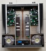
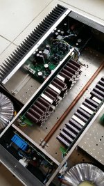

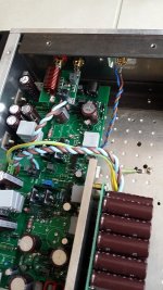
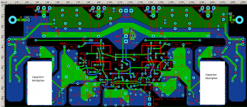
Let me know if you find any obvious errors in layout, wiring, etc.
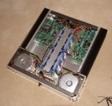
This is my second attempt to build the amp. For the time being it sounds worse than its previous build that seemed to violate all the good design principles. A photo of the first build is attached below.
I don't know what I have done wrong.
This is my second attempt to build the amp. For the time being it sounds worse than its previous build that seemed to violate all the good design principles. A photo of the first build is attached below.
I don't know what I have done wrong.
Attachments
Capacitors necessarily and inevitably must be installed on Board a powerful amplifier. This will reduce magnetic interference from leaking through the wires the power of the distorted currents on the input circuit of the amplifier. For the same purpose the power supply circuit high current output transistors should be covered with solid GND-polygons.
We, Russians, are doing it for a long time and with great success. 🙂
With appropriate circuitry to a powerful amplifier and it is allowed to reach the level distortion -110...-120 dB.
We, Russians, are doing it for a long time and with great success. 🙂
With appropriate circuitry to a powerful amplifier and it is allowed to reach the level distortion -110...-120 dB.
What for?We want low impedance power supply at AF as well as at RF.
Assume a 250 W Amp, this gives a peak current of 11 A in 4 Ohm.
Any R lower than 0.2 Ohm is good enough, as the peak voltage drop of 2.2 Volt is insignificant.
With low series R you have a very high charge current.
You need a bigger transformer as the pulses have a high RMS value.
The pulses will easily couple in sensitive circuit.
No - i don't want a low impedance power supply.
It is better to decouple sensitive circuit with a local regulator.
For RF blocking use an EMV filter at the inlet - it is build for this.
If you use the wrong rectifier diode you will need 10 nF across the secondary
windings. This will help with EMV issues due to microcontrollers too.
This trick is useless due to the long traces involved with big capacitors.The old trick was to parallel film / ceramic caps with electrolytic caps but modern electrolytic caps have low ESR and low ESL therefore can work pretty well themselves. They don’t require paralleled film / ceramic caps, the latter of which can cause impedance peaking / resonance due to LC resonance formed between PCB tracks and internal LCR of the low impedance capacitors. This has been covered in lengthy discussions in the past and I have learnt a great deal from them.
The right way is to decouple sensitive circuits (which maybe need low impedance) directly at the opamp or high-speed transistors.
As soon as you have a few centimeters of wire going off the power plane theOn the other hand, having read from a lot of posts about the benefits of capacitor array on power and ground planes I have experimented rebuilding my preamp and power amp with such power supplies – having some copper zones (small or large) of local power and ground planes on the PCBs with numerous smaller value low ESR and low ESL capacitors on them up close to the active devices they power. I thought that the power and ground planes provide very low inductance current path and along with multiple low ESR low ESL capacitors they provide a very low impedance power supply. But so far the result has not been positive. I can measure low level resonance in the tens of MHz region. The resulting amplifiers sound worse than before.
low impedance is gone.
C = 8.8e-12 * 4 * A / d, or about 220 pF / decimeterI have limited measurement capability and limited knowledge hence my question here. But I have just thought of one thing I did not think of – the power and ground planes on which the cap array is built possibly form a small value, very low ESR, very low ESL, very high Q capacitor! (or does it?) Using a simple LCR meter I measured from 200pF to 1.2nF capacitance between the planes. So my guess is that this high Q capacitor formed by the planes reacts to the LCR of the low impedance cap array, the scenario is exactly the same as paralleling film / ceramic capacitors with low ESR capacitors in our old trick! Or not?
... not much of use in relation to > 5 mF Elkos
Of course, I can be completely wrong. I am here to learn. If you have working experience and knowledge please help me to understand the issue and find a solution. Perhaps I should keep the ground plane but ditch the power plane?
Yes, you are completely wrong. But we are here to learn 🙂
Put some of the saved money in a bigger transformer and better output transistors.
We want low impedance power supply at AF as well as at RF
It looks like everyone is against this. So I am likely wrong.
I guess I expressed it incorrectly. I actually thought that low impedance at higher frequencies was more important, and less important at lower frequencies, hence the CLRCLRCLRC design, which attenuates RF much better but increases DC impedance and keeps RF impedance the same. This is in considerations of amplifier's PSRR getting worse and worse towards higher frequencies.
Using the LTSpice modelling I have obtained the amplifier's PSRR figures.
For the IPS and VAS combined, PSRR has the following figures:
20Hz -> -69dB
50Hz -> -69dB
100Hz -> -69dB
200Hz -> -68dB
500Hz -> -64dB
1,000Hz -> -59dB
2,000Hz -> -53dB
5,000Hz -> -46dB
10,000Hz -> -40dB
20,000Hz -> -34dB
50,000Hz -> -26dB
100,000Hz -> -20dB
For OPS, PSRR has the following figures:
20Hz -> -131dB
50Hz -> -122dB
100Hz -> -116dB
200Hz -> -111dB
500Hz -> -103dB
1,000Hz -> -96dB
2,000Hz -> -91dB
5,000Hz -> -83dB
10,000Hz -> -76dB
20,000Hz -> -70dB
50,000Hz -> -63dB
100,000Hz -> -57dB
Because the IPS and VAS stages have much poorer PSRR, I am employing a capacitor multiplier with low output impedance to help. The OPS stage has good PSRR at low frequencies (so the increase of the PSU impedance due to CLRCLRCLRC does not matter) but it gets poorer at higher frequencies.
Subjectively, after I completed the first build, I experimented changing various big reservoir caps, and found that the lower the impedance of the caps, and the larger values of the caps, provided the better sound. How? I suspect that ripples are reduced and RF filtering is better and PSU impedance is lower.
I understand that low PSU impedance is destroyed if there is a wire between the PSU and the active devices. It is for this reason I have a small capacitor array of 5 x 680uF low ESR low ESL capacitors on power and ground planes right at the LMOSFETs, and this should provide low inductance. This replaces the traditional 100nF film capacitor near the LMOSFETs. I was hoping that this works but I suspect it doesn't due to potential resonance (somewhere probably come from the cap array either on the amp board or on the PSU board).
Attachments
Last edited:
- Status
- Not open for further replies.
- Home
- Amplifiers
- Solid State
- Capacitor Array on Power and Ground planes – How to Avoid Resonance?