Hi, thanks for that midrange, Google leads me to the original Kef CodaThe original Kef Coda had those drive units, hence my mentioning of it. It also had a very simple crossover!
The Coda (1971-77) was developed from the ground breaking Cresta design with some useful design elements to provide excellent acoustical performance in an economic package. Its accurate, wide frequency response made it ideal for high quality stereophonic systems in small to medium sized rooms and the dimensions allowed convenient installation in the new, but short lived, quadrasonic format.
Specification: Two-way, bookshelf
Enclosure type: Closed box 330 x 230 x 146 mm (13 x 9 x 5.75 inches), 5kg (10.4 lb)
Input Impedance: 8 ohms
Rated maximum power: 20W programme
Amplifier Requirements: 15-20 watts per channel into 8 ohms
System resonance: 60Hz
Frequency range: 50-40,000Hz
Crossover Frequency: 3500Hz
System: SP1034
Drive units: B110 bass unit (SP1003), T27 tweeter (SP1032)
Crossover: SP1035
That gives me some more data on cabinet dimensions and volume; now what I need to do next is get the spec for the SP1035 crossover 🙂Specification: Two-way, bookshelf
Enclosure type: Closed box 330 x 230 x 146 mm (13 x 9 x 5.75 inches), 5kg (10.4 lb)
Input Impedance: 8 ohms
Rated maximum power: 20W programme
Amplifier Requirements: 15-20 watts per channel into 8 ohms
System resonance: 60Hz
Frequency range: 50-40,000Hz
Crossover Frequency: 3500Hz
System: SP1034
Drive units: B110 bass unit (SP1003), T27 tweeter (SP1032)
Crossover: SP1035
There are so many speakers and crossovers with versions of the KEF B110 and the T27, that I get quite a headache. 😀
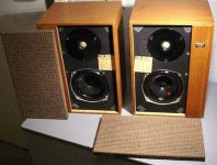
I think they were the Coda, Cresta, Caprice, CS1A and R101.
The first ones like the pictured Cresta used just a bass coil and a second order tweeter. 4uF IIRC. Don't know the coil values.
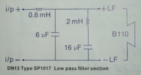
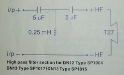
Here's the DN13 SP1017 schematic which should work with your drivers. The 2mH coil has a built in 6.4R resistance to make the notch work.
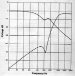
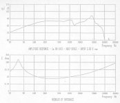
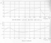
The later CS1 electrical response shows what KEF got up to, here with an acoustic butterworth notch on the tweeter. Complicated stuff!
I think they were the Coda, Cresta, Caprice, CS1A and R101.
The first ones like the pictured Cresta used just a bass coil and a second order tweeter. 4uF IIRC. Don't know the coil values.
Here's the DN13 SP1017 schematic which should work with your drivers. The 2mH coil has a built in 6.4R resistance to make the notch work.
The later CS1 electrical response shows what KEF got up to, here with an acoustic butterworth notch on the tweeter. Complicated stuff!
Attachments
Last edited:
I think you must be careful which version of the B110 you are dealing with on a complex filter.
KEF CS1, 101 CROSSOVER, KEF B110B SP1057 T27 SP1032 with HIGH POWER LF SECTION
The original B110A SP1003 and later B110B SP1057 are different animals on frequency response though mechanically similar. But the T27 SP1032 tweeter seems consistent.
Attachments
Here's what KEF say:
Explore KEF - Constructor Series CS1 to CS9, PL301 - KEF International
Constructor Series Model CS1 (1981-90)
The CS1 was a bookshelf two-way system based on the Reference Model 101
B110B SP1057, front mounted in 12mm Chipboard 8L. Positive polarity crossover.
Constructor Series Model CS1A (1981-90)
The CS1A was a bookshelf two-way system based on the BBC LS3/5A.
B110A SP1003, rear mounted in 12mm ply 8L. Negative polarity crossover.
Both employ KEF's own acoustic butterworth third order filters.
Thanks for that input System7 and Colin. As it happens, I have managed to find photos of the Coda SP1035 crossover and it seems pretty basic.

I have also seen the details of the Kef recommended crossovers for the B110 & T27 as linked above by System7 and they seem significantly more complex which is odd since all of this comes from Kef.
I am pretty confident that my B110s are the SP1003 versions so the CS1 crossover is probably not suitable. The crossover for the CS1A is the SP2015 and I will try to find details for that.
In the case of the Kef recommended crossover designs for the B110 & T27, I have priced up the capacitors (2 x 5.0 uF, 6.0 uF & 16.0 uF capacitors) and inductors (0.25 mH, 0.8 mH & 2.0 mH) and they work out more expensive than I would have anticipated. Is the design of a passive 2-way crossover a function not only of the drivers involved but also of the cabinet in which the drivers are placed? Specifically, if I were to use the Atkinson Mini Transmission Line cabinet design, would the LS3/5a crossover design work satisfactorily?
Incidentally System7, you say that the "2mH inductor has a built in 6.4Ω resistance", how is this arranged? Does it involve a resistor in series with the inductor?
Last edited:
Incidentally System7, you say that the "2mH inductor has a built in 6.4Ω resistance", how is this arranged? Does it involve a resistor in series with the inductor?
An inductor has a resistance due to the significant length of wire in them
dave
So not really selectable then? When I read adverts for inductors, I don't see any option to choose a particular resistance although the resistance seems to be quoted. I guess it would be different if you could roll your own.An inductor has a resistance due to the significant length of wire in them.
One can reduce the R by choosing an inductor with fatter wire (althou they often end up bigger (gretaer length of wire) so it isn't a straight gain) or using a cored inductor.
dave
dave
So not really selectable then? When I read adverts for inductors, I don't see any option to choose a particular resistance although the resistance seems to be quoted. I guess it would be different if you could roll your own.
Falcon Acoustics gives you the typical DCR for each of their inductors if you look at the individual product description.
Falcon Acoustics | The Leading DIY Speaker Parts and Kit Supplier since 1972
Indeed it does, but one cannot select / specify a desired resistance although I realise that you can always increase the resistance by placing a resistor in series 🙂Falcon Acoustics gives you the typical DCR for each of their inductors if you look at the individual product description.
Falcon Acoustics | The Leading DIY Speaker Parts and Kit Supplier since 1972
However, this doesn't really help me to decide what the effective differences would be if one used the Kef Coda crossover, one of the many Falcon LS3/5a crossovers or the crossovers suggested by Kef for use with the B110 & T27 as referenced above by System7. To repeat my earlier query:
Is the design of a passive 2-way crossover a function not only of the drivers involved but also of the cabinet in which the drivers are placed? Specifically, if I were to use the Atkinson Mini Transmission Line cabinet design, would the LS3/5a crossover design work satisfactorily?
Air core inductors have greater resistance vs their cored counter parts. Cored inductors induce hysteresis that adds distortion, especially at higher power levels, but due to the increased inductance require shorter lengths which equates lower resistance. Typically we want lower resistance, but not all designs require the lowest that can be had. From this we have all varieties of air cored which range from the typical round magnetic wire, hexagonal, and flat ribbons. Normally the higher end (read least resistance) esoteric types cost an arm and a leg, especially as value increases.
Best to model design and change the resistance value of the inductors to see what changes best fit the bill. Remember resistance also influences voltage level delivered to the speaker, if too high will impact acoustical balance between drivers and change the actual crossover point causing a mismatch if excessive.
Best to model design and change the resistance value of the inductors to see what changes best fit the bill. Remember resistance also influences voltage level delivered to the speaker, if too high will impact acoustical balance between drivers and change the actual crossover point causing a mismatch if excessive.
Or do an active crossover for bass only.
That avoids the very large inductors and the very large cost.
That avoids the very large inductors and the very large cost.
Thanks for that Greebster, I must admit I had been wondering about the reason for the greater cost of air cored inductors. Do you think there is any point in a complete novice trying to get to grips with Jeff Bagby's Passive Crossover Designer software?
To be hoenst, I can't see that active crossovers would be cheaper than passive even if they do offer greater flexibility (tweaking).Or do an active crossover for bass only.
That avoids the very large inductors and the very large cost.
As far as I'm concerned, a 2pole jFET active filter costs a little bit more than peanuts.
And I use lsk170. there are cheaper jFETs.
One could use the cheaper end of the jFET opamps. opa2134, or opa134 and many others.
And I use lsk170. there are cheaper jFETs.
One could use the cheaper end of the jFET opamps. opa2134, or opa134 and many others.
This requires a proper model in Spice of the loudspeakers used... otherwise it's a very raw method..Best to model design and change the resistance value of the inductors to see what changes best fit the bill. Remember resistance also influences voltage level delivered to the speaker, if too high will impact acoustical balance between drivers and change the actual crossover point causing a mismatch if excessive.
Regarding the Atkins mini TLS, yes other crossovers would work as long as the mounting distances between the drivers are similar as is baffle with and distance from the top edge. The longer front baffle below the B110 does add some baffle loading but I would prefer most crossovers to the original Atkins thing.
Working on the assumption that we are talking about the Atkinson Mini Transmission Line Speaker here, it was designed using an Isophon KK8 rather than a Kef T27 as the tweeter so the original crossover may well not be ideal for my proposed variation.Regarding the Atkins mini TLS, yes other crossovers would work as long as the mounting distances between the drivers are similar as is baffle with and distance from the top edge. The longer front baffle below the B110 does add some baffle loading but I would prefer most crossovers to the original Atkins thing.
I think I should be able to place the T27 pretty much wherever I like but the overall dimensions are significantly greater than the LS3/5a and I would want to position the B110 as shown in the design description (because of the Transmission Line). The Kef crossover designs make no mention of the front baffle dimensions or the positioning of the drivers.
What is the relationship between a crossover and the distance between the drivers and the distance from the top edge? Surely it is all about cut-off points, roll-off, resistance and SPL and the cabinet is designed to get the best results from the chosen drivers?
Read all this with great interest. I built myself a pair of LS3/5a using drivers from a pair of Kef concerto's I got from a skip. I read all the available documentation regarding the original design concept and made them as close as I could (cabinet material damping etc) to the specs. I used crossovers from Falcon which I was told suited best the drivers I had which were of course not selected. I had never heard any other LS3/5a's so I had no yardstick to compare them to. I love them, not because they are better than other more modern designs but because they did then and still do now exactly what the were designed to do, be small monitors for use in O/B trucks which would have very low colouration and thus not fatigue the listener. Harwood and co did a wonderful job of what they were asked to do and the popularity of the speakers came later when commercial units were produced. Let's not try to make a better LS3/5a just respect how good it was in it's day at doing the job it was designed to do.
They are the only speakers I have ever made which I would not break down later to make something else, they are sacred.
They are the only speakers I have ever made which I would not break down later to make something else, they are sacred.
Cabinet size, driver positioning and crossover can be interlinked, depending on the sophistication (or over-complexity) of the design. I know one commercial manufacturer who achieves excellent results without worrying about it, prefering to leave the drive units unimpeded to do their own thing.
Regarding active crossovers - these days they can be cheaper and less bulky than a passive crossover. There are some interesting-looking kit and ready-made versions available from this UK-based eBay vendor
kevinmount | eBay
The amplifiers needn't be expensive either - for instance, a good chip amp. Don't forget you can use smaller output to each of the drivers than you would need if using one amplifier driving a passive crossover.
Last edited:
- Home
- Loudspeakers
- Multi-Way
- Can one build a better (non) LS3/5A speaker based on T27s & B110s?