Sorry for creating errors guys,I guess sleep deprivation.
So here is my understanding about Calvin's buffer with servo. All part numbers I describe are based on Calvins schematic in post 15.
Servo being used because there is voltage offset between input and output.
In original design without servo a Trim pot is used across R8 to correct it. But my understanding is ,over the time and due to temperature offset can change. I guess that means if I set trimpot , after circuit has been running for sometime, there still will be an offset when I turn it on next time until fets are warmed up. Also over the time I need to make sure there is no drift due to aging.
The current through buffer is determined by two resistors R7 and R12. In servoed version the R12 is about 10% lower made by R12b to create an offset to trigger the servo. Calvin described in post #15 how to calculate a suitable resistor to control current through R20. To simplify it is the positive supply voltage/ (1/10th of buffer idle current). My schematic idle current is near 33ma. so 10/3.3=3K.
Idle current is measured across R7.
My last schematic has mistakes.Attached is the corrected one. What do y'all think about this one?
To ElFishi,
I have simulated Taylor follower and found to have higher THD. With Calvins design THD is very low with Z out close to 9Ohms. so why go after TCS follower?
There's still an error in the servo. The C should be grounded.
Jan
Hi,
jauu
Calvin
I don´t know how You´d do it, but I won´t 😛how would I implement that dual opamp design in your circuit?
jauu
Calvin
Jan ,If you are referring to 1u and 100u caps ,they are connected to net 20,which is the ground of power supply rails.There's still an error in the servo. The C should be grounded.
Jan
So I guess it does not make an audible difference, that's why?Hi,
I don´t know how You´d do it, but I won´t 😛
jauu
Calvin
Here is my input section modified as ElFishi suggested. Is it ok? Is C7 needed ?
Attachments

Last edited:
Jan ,If you are referring to 1u and 100u caps ,they are connected to net 20,which is the ground of power supply rails.
OK, didn't know that.
Jan
Hi,
Go to #31, add the 2uF cap at the wiper of the Pot, add the 1M from the cap to gnd and series connect a 100R towards the Gate (similar to the lower part's gate).
Increase the series input 10uF cap such that it gives a sufficiently low bandwidth limit together with the 10k pot.
jauu
Calvin
Nope.Is it ok?
Go to #31, add the 2uF cap at the wiper of the Pot, add the 1M from the cap to gnd and series connect a 100R towards the Gate (similar to the lower part's gate).
Increase the series input 10uF cap such that it gives a sufficiently low bandwidth limit together with the 10k pot.
jauu
Calvin
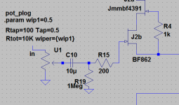

If you are going 10uF you can go down with R19.
20k will still give you a cutoff frequency below 1Hz and less EMI pickup by J2b.
These BF862 are designed for AM radios after all.
20k will still give you a cutoff frequency below 1Hz and less EMI pickup by J2b.
These BF862 are designed for AM radios after all.
I don't want to use 10u as they are expensive. But slightly confused with RC filter concept . Is the filter formed by potentiometer and cap or is it 1meg and cap, or both shares cap to form filters?
Hi,
use a Schottky, low power, like BAS85 or LL103C (Diotec).
It´s important that the Vf of the diode is low, so that in case that when at start-up a condition occurs, where the Gate-Source voltage of the JFET might become positve -resulting in drain currents >> Idss- the Vgs stays low enough, that the JFET doesn´t latch-up and survives.
It shouldn´t d be necessary and I haven´t seen a protection Diode in Nelson Pass´s or Erno Borbely´s circuits (to name just two JFET implementors), but I had a couple of cascoded JFET-only Buffers that latched at start-up and were safed with the diode.
jauu
Calvin
Thanks Calvin. I am in the process of making PCB now. I will be using using mostly non-Smd resistors ( for ease of handling and some for non availability of thin film resistors ). It seems like some traces will be routed through lower surface of pcb. Which all traces should be made really short and should be kept on same surface. Routing power supply traces mostly on undersurface now .
Hi,
for most parts I find SMDs easier to solder.
A SOT23 transistor for example has a similar footprint as a TO92 throughhole.
Either glue the parts on the PCB and solder after drying, or just solder one pin, correct for the position and then solder the rest.
Resistors from 0805 size are absolutely easy to solder ... better than throughhoöles ... no need to bend wires, fiddling of pins through tiny holes, tuning over the PCB, fixing the part somehow from falling off again, eventually soldering and of course burning the finger that held the part in place, cutting the pins which off course careen cross the room and vanish in the carpet floor where You will never find them again till the day You walk with naked feet ....
No no, throughhole is often a real pita ahem pitf...imho.
jauu
Calvin
(pitf - pin in the foot) 😉
Last edited:
Calvin for some parts there are only thick film resistors available. Also the thin film parts are x4 expensive than through hole parts. I understand the point you are making. I will give it a try again.
I am thinking of a power supply for the board and like to have it on board. LT3024 seems like a nice candidate with the virtual ground. What do you think?
I am thinking of a power supply for the board and like to have it on board. LT3024 seems like a nice candidate with the virtual ground. What do you think?
If I were going to design a board for this buffer, I would use regular 'ole .25W through-hole resistors and forget about the SM resistors and all the nonsense about about sticking cut off leads through your foot.
I've built a couple(without any type of servo) with Vishay RN55 resistors and they worked without any issues.
The first Calvin buffer I built did use SM resistors and used a board designed by Rudi Ratlos.
It used 1206 resistors and took more time trying to soldering them into place than comparable through-hole resistors would've taken.
Had Rudi's board required 0805 resistors, I wouldn't have wasted my time trying to solder such small resistors in place.
Hi,
thanks, just needed someone like You to tell me talking nonsense 🙄
Now I´m happily ´grounded´ again 😛
jauu
Calvin
thanks, just needed someone like You to tell me talking nonsense 🙄
Now I´m happily ´grounded´ again 😛
jauu
Calvin
Hi,
I searched into my notes about the diodes and found these:
BAS85 (SOD80, Vishay, Diodes, NXP et al), NXPs PMEG2005ESF and PMEG3005ESF in SOD962-2, or NXP 1PS76SB21 in SOD323, or maybe Diodes DFLS130L in PowerDI123.
The LT3024 is a dual positive reg not useable in this application.
The LT3032 could be the part of choice ... beware though it only comes in a tiny DFN4x3mm 14-pin package that You can´t solder with an iron any more.
It´s a dual pos/neg Lowdropout lownoise Reg.
I used it quite successfully in a project before ... but beware the corresponding app-note (which I can´t find any more, neither on the website nor on my comp. ... it dealt with a floating suppl configuration and contained several failures. Maybe my complaints finally helped and they took it off).
It´d probabley easier to use the TI TPS-series of lownoise LDO-Regs.
As a suggestion for a compact supply, see for dc-dc converters.
Murata has a couple of small 1-3W converters with excellent parameters, like MEV1 (lowest ripple), MEE1 and MEE3 series and NME1.
add a 5 or 12V wallwart and You´re done wih a good supply.
jauu
Calvin
I was thinking something like in post 919.
"The Wire" Official Boards for All Projects Available Here! BAL-BAL, SE-SE, LPUHP
"The Wire" Official Boards for All Projects Available Here! BAL-BAL, SE-SE, LPUHP
Hi,
a supply with the LT3042 LDOs is certainly interesting (will be quite difficult to solder)
Have You had a look at JanDidden´s Silent Switcher?
jauu
Calvin
a supply with the LT3042 LDOs is certainly interesting (will be quite difficult to solder)
Have You had a look at JanDidden´s Silent Switcher?
jauu
Calvin
- Status
- Not open for further replies.
- Home
- Source & Line
- Analog Line Level
- Calvin buffer with servo