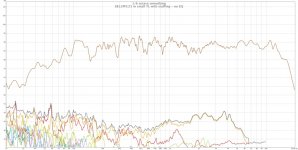
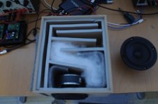
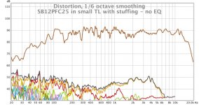
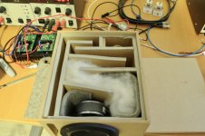
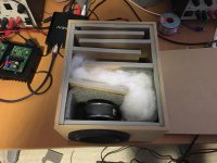
The little SB12PFC25 shows rather a lot of promise in a small TL (no chamfers). Attached a couple of photos, plus plots with no EQ and with a 6dB boost below 80 Hz. Given the intent is to use a number of these in a line, less EQ is likely to be needed because of the larger baffle.
Oh, and I reckon that's 40 Hz 😛
I really like these little SB drivers. They go in and out rather a long way.
Next to test the SB12NRX25, which is the aluminium basket, poly cone version of the SB12PFC25. They're completely interchangeable.
Oh, and I reckon that's 40 Hz 😛
I really like these little SB drivers. They go in and out rather a long way.
Next to test the SB12NRX25, which is the aluminium basket, poly cone version of the SB12PFC25. They're completely interchangeable.
Attachments


Last edited:
...plus plots with no EQ and with a 6dB boost below 80 Hz...
Oh, and I reckon that's 40 Hz
Looks like down 20 dB + 6 dB of EQ = down 26 dB @ 40 Hz.
dabe
Looks like down 20 dB + 6 dB of EQ = down 26 dB @ 40 Hz.
dabe
What? I don't understand. The plot is 5dB per div.
Looks like 10 on 1st glance at the low rez it is posted. Looking at it again, -18 dB once the EQ is factored out.
dave
dave
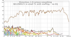
SB12NRX25 plot attached - exactly the same setup as the PFC version.
Bass is essentially identical between the two - near as I can tell the motor is identical - NRX version has significantly lower distortion in the mids, I guess due to the poly cone, but loses the plot at 10KHz.
Bass is essentially identical between the two - near as I can tell the motor is identical - NRX version has significantly lower distortion in the mids, I guess due to the poly cone, but loses the plot at 10KHz.
Attachments
Here's a few plots changing the length of the TL, by shortening the last hairpin.
There's a definite improvement from 120cm to 110cm, no real difference from there to the current 102cm length.
All plots have no EQ applied.
There's a definite improvement from 120cm to 110cm, no real difference from there to the current 102cm length.
All plots have no EQ applied.
Attachments

Nice work SuzyJ. 
If you somehow add another layer of wood with a hole to flush mount that baffle, you will probably fix (3-5dB dips/peaks) or maybe about 80% of this wiggles in the 600Hz to 5kHz range and it will sound a lot smoother. Those are caused by baffle diffraction and that thick driver bezel step.
If you somehow add another layer of wood with a hole to flush mount that baffle, you will probably fix (3-5dB dips/peaks) or maybe about 80% of this wiggles in the 600Hz to 5kHz range and it will sound a lot smoother. Those are caused by baffle diffraction and that thick driver bezel step.
On to prototype 2. I thought it'd be useful to try the vent at the back rather than the front. I decreased the total width to 20cm from 21cm, but because I no longer have the 16mm channel from the back to the front the length of each line section is 12mm longer, so the overall length is about 106cm, which was one of the lengths I tried when modifying the first prototype.
I also went from 12mm lid and base to 6mm lid and base, on the basis that these will be stacked, and the thick lids and bases make no sense. This made the channel 12mm higher, increasing the CSA by about 10%.
First observation is that the rear vent speaker is much more fussy about where I place the speaker on the desk for testing I think the 160Hz hole is mostly due to reflections from the rear wall - I can move the hole around by changing the distance from the speaker to the wall.
Also the increase in CSA appears to increase the line Q, so it's got about 3dB more SPL at 50Hz, but 3dB less at 65Hz.
Attachments


Nice work SuzyJ.
If you somehow add another layer of wood with a hole to flush mount that baffle, you will probably fix (3-5dB dips/peaks) or maybe about 80% of this wiggles in the 600Hz to 5kHz range and it will sound a lot smoother. Those are caused by baffle diffraction and that thick driver bezel step.
Yes this is certainly the intent for the final speaker. For now I'm just interested in what's happening down low, so reducing diffraction isn't terribly important. These prototypes are pretty rough.
If strictly for prototyping, foam core (if available locally) and hot glue are excellent and fast. But a design like this is fully predicted using modeling tools like Akabak without having to build.
It's fun though to cut and glue and listen. Akabak would have shown that the rear vent makes wall placement very sensitive to position.
It's fun though to cut and glue and listen. Akabak would have shown that the rear vent makes wall placement very sensitive to position.
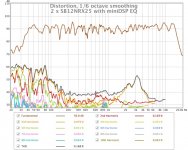
So a pair of these stacked on top of one another 5cm from the wall and driven via a miniDSP is actually getting rather good.
I set the level to 90dB at 1m so I can compare with previous plots I've done of my Ariels. The distortion levels is quite comparable, despite the huge difference in size between the two speakers.
My Ariel plot is at http://www.diyaudio.com/forums/mult...-scan-speak-d2905-950000-a-2.html#post5108838
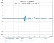
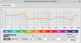
I've also attached a plot of the impulse response and a screen-grab of the EQ.
I set the level to 90dB at 1m so I can compare with previous plots I've done of my Ariels. The distortion levels is quite comparable, despite the huge difference in size between the two speakers.
My Ariel plot is at http://www.diyaudio.com/forums/mult...-scan-speak-d2905-950000-a-2.html#post5108838
I've also attached a plot of the impulse response and a screen-grab of the EQ.
Attachments
Last edited:
Final speaker (with tweeter added - the shame!) over in the multi-way forum:
noiseUnit - transmission line computer speakers.
noiseUnit - transmission line computer speakers.
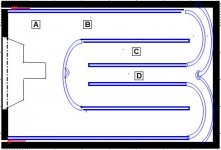
Is this a good design for a small TQWT?
See pic below,. By the way, Suzyj, those are nice looking speakers.
I would like advice before I build this enclosure for a near field enviroment. It has a line length about 28 inches times 2 lines = 56inches with a tapered ratio of 1/10 (but does that second line count in the length?).
1. It will either have an outside of 1/2" plywood with 4 ea 3/16" PVCheated bent strips for the line.
Or
2. Made out of foam core since XRK971 has gotten meinterested in that.
OD dim = 5w x 7h x 10d, ID dim = 4 x 6 x9
Gross Vol about 216 cu in, net about 180 cu in
I have all 5 drivers and want to exchange/experiment with them – What do you think about how these will perform (under 200Hz) in this enclosure?
a. AuraSoundNS3-193-8A 3"Fs=80Vas=76 cuinQTS = .67
b. Dayton Audio ND90-8 3-1/2"Fs=71Vas=107 cuinQTS = .65
c. Fountek FE83 3"[/FONT][/COLOR]Fs=71Vas=107 cuinQTS = .65
d.Tang Band W3-2108 3-1/2" RBM \Fs=45Vas=103 cuinQTS = .46
e. Peerless by Tymphany TC9FD18-08 3-1/2"[/FONT][/COLOR]Fs=125Vas=89 cuinQTS =.46
Taper- Height of B = 1.25 x 4 inches = CSA=5 inches. Terminus is .125 x 4 inches = CSA= .5 inchestimes 2 of them = 1 inch
Instead of a BSC, I will be using a windows tablet with the Peace parametric equalizer with a low/ high shelf, cutting the peaks and gentlecut of the highs.
Questions:
1. Does the line length extend from B to A or starts at B?
2. Duplicate lengths: Is this really a 56 inch line or just a 28 inch line with two openings? If just 28, then I will redesign for a longer single line unless someone gives me a reason to have two lines.
3. There would be a major resonance since the driver is not1/3 of the way down the line or does this twin line enclosure help that?
4. Would offsetting the spk to the very top help?
5. If using one of the drivers above with a higher fs, howmuch shorter should the line length be, if any?
Thanks for any advice,
Attachments
Last edited:
First TQWT refers to a Voigt pipe which starts small and gets larger. This is a stepped taper TL.
Line starts at A. How long is it? My impression from th epic is that it is long for those drivers. As well it does not take advantage of driver offset to get a better preforming line.
dave
Line starts at A. How long is it? My impression from th epic is that it is long for those drivers. As well it does not take advantage of driver offset to get a better preforming line.
dave
It's 28 inches with two openings. I quite like the design - symmetry always does it for me.
28 inches probably isn't that far out of the ballpark for these small drivers. This one has a lot of taper, so probably has a pretty low resonant frequency. It'd be easy to prototype it in a way that you could play with the line length, by making blocking sections up to shorten the C-D length, similarly to how I played with my initial prototype.
I think offsetting the speaker is of more use in a simple long tube or single fold. Multiple folds helps attenuate higher frequency content (in much the same way as stuffing), without the extra volume needed.
I wouldn't bother with the rounded bits - just make it square and throw some felt in if needed.
It's 28 inches with two openings
Yes, that is in the ballpark. Tuning frequency <120 Hz.
I think offsetting the speaker is of more use in a simple long tube or single fold. Multiple folds helps attenuate higher frequency content (in much the same way as stuffing), without the extra volume needed.
It is applicable no matter the number of folds and requires no extra volume/
I wouldn't bother with the rounded bits - just make it square and throw some felt in if needed.
+1
dave
Thanks for the response
Based on what you’ll said:
Based on what you’ll said:
- Is there any reason to have two lines as I can make the volume less by eliminating one of them?
- I don’t need to model it since I will build an adjustable enclosure but if I use the peerless Tc9fD18 which has a nice mid to top range and a 105fs, qts=.46
- about what tapered length should I start with?
- And what CSA should I start with?
- And if I have only one line, and place the speaker down 1/3, would one inch behind the magnet be enough for the speaker to breathe?
- Am I right that the lower the Fs and the higher the Qts, the longer the line can be or does the QTS matter if the driver has a large Xmax?
Is there any reason to have two lines as I can make the volume less by eliminating one of them?
No.
I don’t need to model it since I will build an adjustable enclosure but if I use the peerless Tc9fD18 which has a nice mid to top range and a 105fs, qts=.46
You need to do some modeling to ensure you are in the ballpark. Optimum for each driver is quite possibly more than the length.
Specifications i find for the TC9 show Qts = 0.89 and Fs = 125 Hz. Measured were at least a little bit higher. IMO suited only for IB or OB. We put ours in an IB and results were disappointing,
- about what tapered length should I start with?
- And what CSA should I start with?
- And if I have only one line, and place the speaker down 1/3, would one inch behind the magnet be enough for the speaker to breathe?
Length & CSA should be determined by modeling them. Proper offset ia dictated by line taper. I have been told Marin King’s SS model won’t handle drivers with Fs > 70 Hz but the correct offset based on taper should still hold.
Am I right that the lower the Fs and the higher the Qts, the longer the line can be or does the QTS matter if the driver has a large Xmax?
Xmax has nought to do with it, lower Fs usually means longer line, Qts value can be used to choose an appropriate taper (that last not hard & fast).
dave
- Status
- Not open for further replies.
- Home
- Loudspeakers
- Full Range
- Calling all T-Line experts – Designing a 40 Hz compact enclosure