Sure, I understand those things - what I meant about innovative are things like:
1. How many helix ports or enclosures have you seen people build vs standard, probably less than 1% - Maybe that is a more efficient enclosure design - smoother air flow vs 45 or 90 degrees.
2. You can do things with 3d printing that wasn't possible 5 years ago
3. I haven't seen many isobaric designs in a T-line which may (probably not) help make the enclosure smaller.
4. There is the cornu design but I haven't seem many spiral T-lines "flat" vs vertical where you might be able to use the corners for a resonance chamber.
5. Then there is the possibility to use inexpensive drivers somewhere in the path to handle resonances better - and with such cheap electronics, maybe even a real time electronic circuit to control those speakers in frequency and amplitude.
6. And with those inexpensive amps, (for a very small T-line who needs the best), we could do in-line (before the amp) all kinds of BSC, DSC stuff to get the most out of less expensive drivers, even controlled by your smartphone for the type of music.
However, I'm bowing out like I said because I can't get a group together to get excited about doing something like this - hopefully, someone that can better motivate people will come in and take over.
Again, I want to thank all of you that posted.
scott
Last edited:
Yeah, when you've read as many patents, doodled/designed intake, exhaust, other types of materials manifolds [TL, horns, some vented], etc., as I have combined with B0$3 staying on the bleeding edge of materials, manufacturing advances, it's hard to generate any continuing enthusiasm after ~64 yrs of it beyond providing enough info for a neophyte to 'plow the same field' as so many others have in the hope that some new hybrid flower will bloom. 😉.
GM
PS: Let's not forget antenna, SONAR design, which has been the most innovative.
GM
PS: Let's not forget antenna, SONAR design, which has been the most innovative.
hopefully, someone that can better motivate people will come in and take over.
Again, I want to thank all of you that posted.
You're welcome!
Note that frictional losses can be significant in some of these designs, so as I previously noted, once you move from the most efficient, you're always trading efficiency for BW and one reason why you see so few of certain types of alignments.
Your perceived lack of motivational skills have nothing to do it! Your timing is just off a few decades for such a mature science. That said, recent enhancements to Hornresp, 3D printers is causing a minor renaissance in [DIY] horn/WG design of some recent patented/proven innovative 'inventions', i.e. they're 'fine tuning' them to suit their apps, so recommend looking to those folks for any 'new' insight.
GM
However, I'm bowing out like I said because I can't get a group together to get excited about doing something like this - hopefully, someone that can better motivate people will come in and take over.
Scott68,
Thanks for your efforts to organize this. I think what you are looking for - a group of people coming together to build something happens first by one person doing it and showing nice concepts, something interesting, energy, and productivity of enthusiasm. Nothing is more contagious than enthusiasm and speed of build. But it always starts with one person's hands on enthusiasm of build.
Rather than bowing out - if you truly want to see this become something more, take the plunge and build us a compact 40Hz TL. Others will follow. To demonstrate a proof of principle concept I suggest using models like you are doing and making quick and dirty prototypes with XPS foam or foam core and hot melt glue. If the measurements show promise with the foamcore proof stage, then dive into wood.
It's nice when parallel builds across the world happen in a thread to show a new design. It's rare though. The Cornu horn was one and the bookshelf point source horn were the two threads where I have experienced this. The energy and speed of build will get a lot of people to be excited and the view meter will skyrocket. Sometimes 700 to 1000 views a day. It's really exciting when that happens and is a sure sign of something cool going on.
So pick your favorite design - improve it via modeling, then build. Good luck.
There are actually original new (patented) alignments out there that cleverly use topologies never before tried that do get around the general rule that fb is dictated by box volume and TL length alone.
Last edited:
Thanks GM and xrk971 for those kind words and directions as well as to Planet10 and the rest of the postors. I'm thinking of taking xrk971 suggestion about just start building. But first, I need to build my adjustable T-line (length, taper, vol and speaker slider) enclosure because I couldn't get an answer to the question about using: old method= Sd2 vs new method QTS/Vas to figure volumes (what program simulates the new method.)
Before I start, if you'll will give me your advice on:
1. Of the drivers that I mentioned in post 46, which would be one that would best meet my design - near field, F3 40Hz, and smallest enclosure? Or if you have another under $25?
2. Of the enclosures in post 59, same question?
3. Will an isobaric combo allow for a smaller vol behind the driver and vol in the line? I realize the line still needs to be a certain length.
Thanks
scott
You're welcome!
Qts/Vas ??? What are you trying to say? Again, you can derive MJK's design math from his alignment tables doc or just use the Excel SS.
GM
Qts/Vas ??? What are you trying to say? Again, you can derive MJK's design math from his alignment tables doc or just use the Excel SS.
GM
I've just bought a pair of SB12PFC25 midwoofers. They've got an Sd of 50cm^2 and claim Xmax of 5mm with fc of 58Hz, so I think they've got a good chance. In my application I'll be using them with tweeters, but they don't appear too tragic as full-range drivers.
Based on published specs, it can only make it in Small's minimum net Vb if EQ'd, otherwise a ~48 Hz/f3 or bigger cab.
GM
GM
Thanks suzj, I looked at those and that seems a good deal - and the prices are all over the place, 18$ to 52$. However, after putting them through the same program in post 46, they require a larger cabinet then two of the others. Gm, about the Vas/Qts = if seems like the reading I'm doing about T-lines suggests that the method of using Sds to calc the vol is not as accurate as using Vas/Qts. However, I can't find any formulas using Vas/Qts.
I would still like opinions on which driver in post 46 and which enclosure type in post 59, would give me the best chance of hitting my goal (even it is impossible) of near field, f3 40hz with the smallest enclosure.
thanks
I would still like opinions on which driver in post 46 and which enclosure type in post 59, would give me the best chance of hitting my goal (even it is impossible) of near field, f3 40hz with the smallest enclosure.
thanks
I'm not following - if you are using a simulation program, which one so I can try different drivers? Also, which driver are you using? A couple of the drivers I have in post 46 have Fs below 60.
...Which does not mean they can achieve that (or lower) with a flat response. Fs is a single characteristic only.
Hornrsp, AkaBak, Martin King's (now unavailable) MathCAD worksheets, the Leonard Audio TL software, Augspurger's Tlwrx can all simulate QW enclosures.
As has been noted, there is zero functional relationship between driver surface area and the CSA at any point in a QW box. Effective Q and Vas dominate the bulk requirements, and for a given tuning frequency as these are reduced from what is optimal for a given alignment so F3 rises.
Here's my plan for a low volume transmission line. SB12PFC25 plus a couple of Vifa NE19VTS tweeters in a small cabinet. Line is 77cm^2 at the driver end and 17.6cm^2 at the open end, with a length of around 1.2m.
The whole thing is intended to be stacked in various heights to make a line array, but obviously the individual unit will hopefully be able to produce reasonable bass without too much eq.
The whole thing is intended to be stacked in various heights to make a line array, but obviously the individual unit will hopefully be able to produce reasonable bass without too much eq.
Attachments
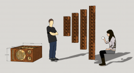
Here's my plan for a low volume transmission line. SB12PFC25 plus a couple of Vifa NE19VTS tweeters in a small cabinet. Line is 77cm^2 at the driver end and 17.6cm^2 at the open end, with a length of around 1.2m.
The whole thing is intended to be stacked in various heights to make a line array, but obviously the individual unit will hopefully be able to produce reasonable bass without too much eq.
Nice design. Did you arrive at this via simulation? Reminds me of a compact TL monitor I made that was inspired by a PMC monitor.
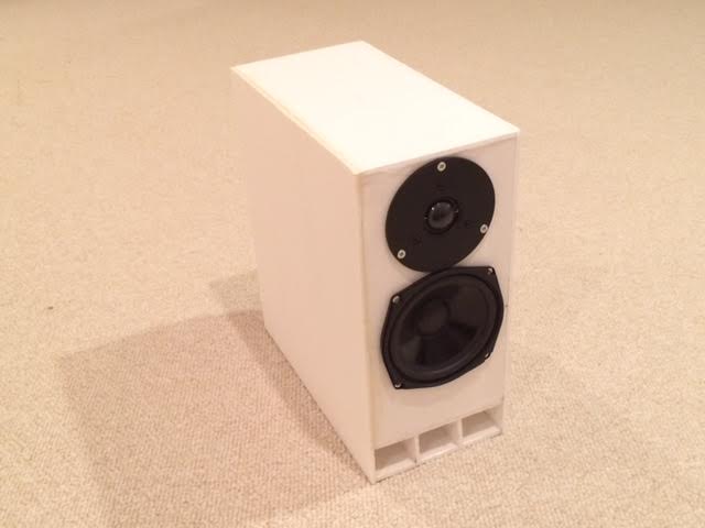
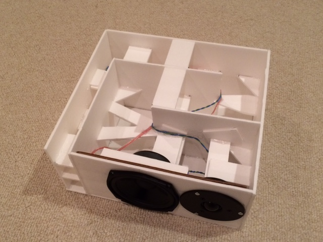
http://www.diyaudio.com/forums/multi-way/281778-low-cost-pmc-inspired-tl-monitor-dc130a-dc28f.html
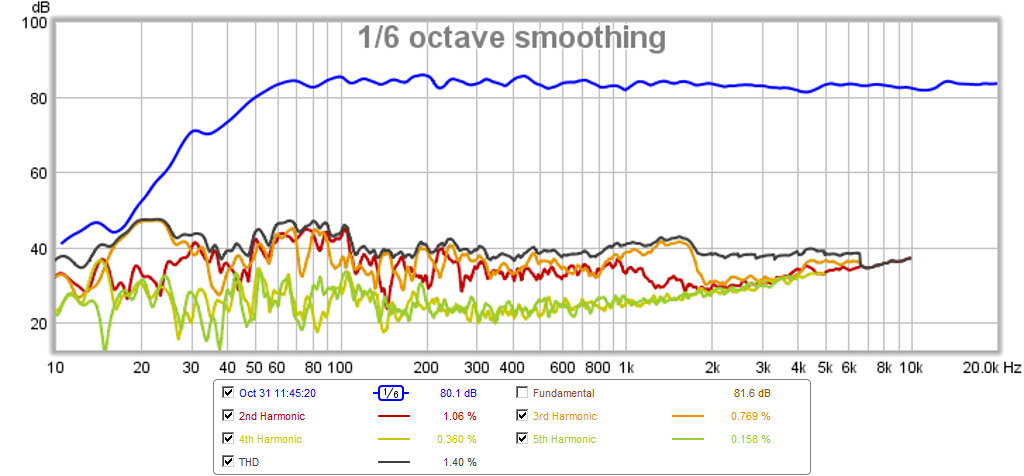
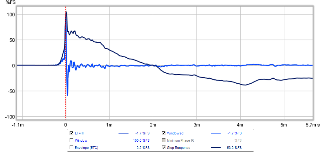
Adjusting stuffing is key to getting a good group delay (here 8.6ms at 50Hz) - the impedance sweep will show a squashed bump with two small bumps on it when tuned just right.

With miniDSP active XO using Harsch setup I was able to get a pretty much transient perfect behavior. Here is step response and impulse:
Last edited:
The thing is, once you have folded up a weakly tapered line as much as you have, you wind up with an acoustic labyrinth, and once properly stuffed, you might as well do a simple sealed box. If you are intending to do a line array, sealed would be a far better answer anyway.
Bob
Bob
Nice to see all the posts - Question from Scottmoose - Based on my research, you are right about CSA being more effected by Vas and Qts so: Where do we find a program that uses those parameters to figure the various volumes needed: above, behind and below the driver?
I like SuzyJ's innovated modular idea - neat. After I get as much info as I can, I'm going with XRK971's idea of a foamcore speaker, maybe with vinyl or something laminated on the outside. What thread/post# starts your build because those graphs look impressive?
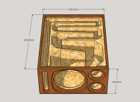
Bob's comment seems reasonable so if I went with a very smooth labyrinth, like the helix (picture below) that I printed with my 3d printer, would that be a better design for a T-line? The one below is a straight T-line but I could vary it to be tapered, I assume the overall taper would be 10:1. Here's what I'm thinking: Use the helix starting just below the speaker so the taper might be (ex. 5 to 1) for the helix. Above the speaker, probably 1/3, would be just a straight pipe or rectangle box. I would use my adjustable T-Line box to get the volumes and length correct before building the T-line. The helix box in the picture below is more complicated to do so would one of the others give the same results?
Xrk971, you are an expert both on foamcore and on T-Lines, what is your opinion about the three designs in the picture?
scott
I like SuzyJ's innovated modular idea - neat. After I get as much info as I can, I'm going with XRK971's idea of a foamcore speaker, maybe with vinyl or something laminated on the outside. What thread/post# starts your build because those graphs look impressive?
Bob's comment seems reasonable so if I went with a very smooth labyrinth, like the helix (picture below) that I printed with my 3d printer, would that be a better design for a T-line? The one below is a straight T-line but I could vary it to be tapered, I assume the overall taper would be 10:1. Here's what I'm thinking: Use the helix starting just below the speaker so the taper might be (ex. 5 to 1) for the helix. Above the speaker, probably 1/3, would be just a straight pipe or rectangle box. I would use my adjustable T-Line box to get the volumes and length correct before building the T-line. The helix box in the picture below is more complicated to do so would one of the others give the same results?
Xrk971, you are an expert both on foamcore and on T-Lines, what is your opinion about the three designs in the picture?
scott
Attachments
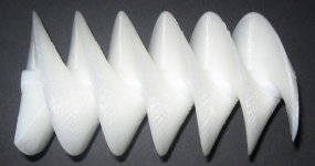

There is no separation of volume above, behind and below the driver in a QW enclosure. There is just volume, as in net bulk. The cross sectional area at different points is a function of this and the chosen line profile (length, taper).
Not that it matters, re the three items in the picture you attach above, the first is a vented box with an unnecessarily complex port, the second appears to be simply a long untapered line with a coupling chamber (sometimes called a daline, albeit with questionable accuracy) and the third is [quite a large] tapped back loaded horn.
Not that it matters, re the three items in the picture you attach above, the first is a vented box with an unnecessarily complex port, the second appears to be simply a long untapered line with a coupling chamber (sometimes called a daline, albeit with questionable accuracy) and the third is [quite a large] tapped back loaded horn.
Last edited:
thanks Scottmoose for staying involved. I didn't make myself clear on both questions:
1. I realize there are not separate chambers in a T-line but the CSA behind the speaker needs to be a certain minimum depth (affecting volume) which then effects the closed end top CSA and then the terminus. So what I was asking, not very well, is how much depth and then side to side, therefore volume, behind the frame opening (not magnet) is needed for a 3 or 4 inch speaker to "breathe." I assume that if the magnet butts up against the back that is ok as long as the width around the frame is large enough. Also, doesn't there need to be a certain minimum volume for the whole T-line in order for the whole t-line concept to work therefore if so, I would expect that the QTS and VAS of the speaker would determine that. Where can I find a program that tells me that volume? I think MLK's info is based on SD2.
2. And again, not well asked, but what I meant was: Because a T-line is a variant of a BR enclosure, which of those designs would be the best "converted" to a T-Line: To meet, closest to my goal, (keyword= closest) of a near field, f3 40hz, most compact enclosure.
thanks
scott
- Status
- Not open for further replies.
- Home
- Loudspeakers
- Full Range
- Calling all T-Line experts – Designing a 40 Hz compact enclosure