In AC analysis, it's just a breeze. In transient mode, when you have an AC waveform with zero-crossings, it is another story. Experts can certainly find a workaround, like the derivative, but the problem will simply be displaced if you use it in a dumb, direct manner: it will occur at inflexion points instead.
You should be able to get a handle on loop gain response by looking at the small signal square wave response, or even better, by employing the Bowes test. The gain and phase response is probably more important than the absolute magnitude.
I would imagine trying to plot dynamic changes in loop gain over the signal excursions would be difficult, but have never had a loop stability problem arise that I could blame on changes to loop gain that could not be deduced from a Bowes test.
I would imagine trying to plot dynamic changes in loop gain over the signal excursions would be difficult, but have never had a loop stability problem arise that I could blame on changes to loop gain that could not be deduced from a Bowes test.
I'm using LoopGain2.asc to check stability. Results seem reasonable except for one piece of confusion. It seems like the probe elements should be within the FB return path, yet this jig has them prior to the load resistor--still in the forward path.There is an example in the LTspice folder examples/educational (the Tian probe is in the file LoopGain2.asc).
Here´s an article from Tian&Co that might help:
https://www.google.com/url?sa=t&rct...d2001-01.pdf&usg=AOvVaw0nOyfB0sz8Je0MQv4xG7jD
A large resistive load by itself doesn't seem to make any difference which side of the probe it's on, at least in my circuits, but the location of a more complex load surely must matter.
I also have some versions of my circuit with local feedback just around the output stage, and this of course makes a big difference whether the probe circuit is located in the forward path prior to the local FB cap/load node or in the feedback path on the other side of the output node. (I know there are some caveats in the Tian/Middlebrook papers about nested loops, but I think that's a separate issue. Nested loops are in the circuit of post #38 and the user reports good results. He also has the input to the probe sources as being the load node, contrary to LoopGain2.)
The short question is where is the right place to insert the probe sources?
Thanks for the great informations ! For me the Tian probe works quite well. Sorry for unearthing the thread but is there a way to get rid of ".step param prb" with the probe still working well? I would need to use .step on others parameters but using two .step at the same time or with tables doesn't seems to give the results expected in this configuration.
Normally you can use two .step directive and they will 'nest', the 2nd one witll step during each step of the first.
Are your epectations correct?
Jan
Are your epectations correct?
Jan
Jan,
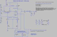
To my question, yes I'm getting the same or nearly the same results. But it seems like where you insert the probe matters, and LoopGain2 has it prior to the load, as it's applied in the circuit shown here. The RETURN LOOP version, attached, is how I would expect it should be: after the load.
So I get the same (or virtually the same) results, but I don't understand why it doesn't seem to matter. Comments, please? Thanks!
Charles
Attachments
I don't see a difference. In both cases, the probe is between the output and the feedback network.
It's just drawn differently.
Jan
It's just drawn differently.
Jan
In one, the circuit is being broken between the output device in the fwd loop, Q5, and the output. (edited for clarity)
In the other, there probe breaks the ckt between that junction and the feedback network. If the probe ckt is lossless (seen as a short), then it would be invisible. Is that what you're saying?
(2nd edit: Also the probe reverses direction in the second case, of course, to follow signal direction.)
In the other, there probe breaks the ckt between that junction and the feedback network. If the probe ckt is lossless (seen as a short), then it would be invisible. Is that what you're saying?
(2nd edit: Also the probe reverses direction in the second case, of course, to follow signal direction.)

Trying to look at it more clearly, the difference seems to be merely which side of the probe's Vi the load (R5, C3, etc.) is connected to.
Tian's probe from LoopGain2.asc is designed in such a way that neither the place where it is inserted into the feedback loop nor the direction matter. The details can be found in the original article "Striving for Small-Signal Stability" referenced by LoopGain2.asc but are a bit complicated for a forum post.
Middelbrook's method from LoopGain.asc is insensitive to where the loop is broken but is sensitive to the direction. This produces error in situations where the signal flows around the loop in both directions (i.e. always in any practical circuit; usually, the effect is small at audio frequencies). Note that LoopGain.asc uses two steps implemented as two separate models, rather than two .STEPs of one model as in LoopGain2.asc.
Both probe location (or rather the impedances on each side of the probe) and the direction of the probe matter if a simple voltage or current source is used as a probe. For example, a single voltage source probe must be connected between a low-impedance "output" and a high-impedance "input" of the loop:

This is discussed in detail in Middlebrook's "Measurement of Loop Gain in Feedback Systems", Int. J. Electronics, 1975, vol. 38, no. 4, pp. 485-512, but is easy to see for yourself in a simulator.
BTW, Tian's formula gives you the phase differently. A simple probe and Middlebrook's show you how the phase changes as the signal travels around the loop. Tian's directly shows you the phase margin.
One more thing: in LTSpice, you can have resistors with one value for AC simulation and another, for everything else. This helps to break loops in AC while preserving operation points and transient analysis. Use them instead of that big inductor.
Middelbrook's method from LoopGain.asc is insensitive to where the loop is broken but is sensitive to the direction. This produces error in situations where the signal flows around the loop in both directions (i.e. always in any practical circuit; usually, the effect is small at audio frequencies). Note that LoopGain.asc uses two steps implemented as two separate models, rather than two .STEPs of one model as in LoopGain2.asc.
Both probe location (or rather the impedances on each side of the probe) and the direction of the probe matter if a simple voltage or current source is used as a probe. For example, a single voltage source probe must be connected between a low-impedance "output" and a high-impedance "input" of the loop:
This is discussed in detail in Middlebrook's "Measurement of Loop Gain in Feedback Systems", Int. J. Electronics, 1975, vol. 38, no. 4, pp. 485-512, but is easy to see for yourself in a simulator.
BTW, Tian's formula gives you the phase differently. A simple probe and Middlebrook's show you how the phase changes as the signal travels around the loop. Tian's directly shows you the phase margin.
One more thing: in LTSpice, you can have resistors with one value for AC simulation and another, for everything else. This helps to break loops in AC while preserving operation points and transient analysis. Use them instead of that big inductor.
Last edited:
With Tian's phase, you still have to get it conventionally though, no? (By subtracting 0dB phase from 180?)
Yes (you'd need to change the sign to subtract like that).
If you look at LoopGain2.asc:

you see that the loop gain phase is 0° at DC and goes negative negative at higher frequencies. The phase margin is the difference between the phase shown for 0dB (about -120° here) and -180°. BTW LoopGain.asc adds a minus sign to the voltage loop gain Gv=-V(x)/V to obtain the same result.
A 0° phase at DC is somewhat counterintuitive for negative feedback. The phase at DC should be -180°, not 0°, and get more negative with frequency. Alternatively, it could be +180° at DC and go more positive as phase lag increases with frequency - this convention is used in some opamp datasheets:

But this is nitpicking. Practically speaking, any convention works as long as no one is confused.
If you look at LoopGain2.asc:
you see that the loop gain phase is 0° at DC and goes negative negative at higher frequencies. The phase margin is the difference between the phase shown for 0dB (about -120° here) and -180°. BTW LoopGain.asc adds a minus sign to the voltage loop gain Gv=-V(x)/V to obtain the same result.
A 0° phase at DC is somewhat counterintuitive for negative feedback. The phase at DC should be -180°, not 0°, and get more negative with frequency. Alternatively, it could be +180° at DC and go more positive as phase lag increases with frequency - this convention is used in some opamp datasheets:
But this is nitpicking. Practically speaking, any convention works as long as no one is confused.
I experimented with a Tian probe and a simple Va/Vb probe and saw very little difference, given that I never put the probe anywhere except between the OP and the negative feedback. And the Tian use of .Step causes problems with certain calculations like using .measure to find the phase margin. I really don't care that you can put a Tian probe in other places. And I am puzzled that a 1Volt stimulus doesn't cause problems in places where that much voltage would cause clipping? Perhaps someday the light will dawn, but for now, I prefer to not use the Tian probe.
Note that the small cap on the feedback resistor is mostly about the impedance of the feedback divider creating an unnecessary (low) pole. I like to parallel both resistors with a ~50 Ohm RC+RC with the same ratio as the DC resistors. This gives a low HF impedance without using high wattage feedback resistor(s). Two pole compensation is popular today, but I would be sure that the design has lots of margin.
Note that the small cap on the feedback resistor is mostly about the impedance of the feedback divider creating an unnecessary (low) pole. I like to parallel both resistors with a ~50 Ohm RC+RC with the same ratio as the DC resistors. This gives a low HF impedance without using high wattage feedback resistor(s). Two pole compensation is popular today, but I would be sure that the design has lots of margin.
AC analysis in Spice uses a linear small signal model, which doesn't include large signal and nonlinear effects such as clipping.I am puzzled that a 1Volt stimulus doesn't cause problems
"Vstim node1 node2 AC 1" doesn't mean one volt, it means one unit of small signal voltage in SPICE AC analysis. Think of it as 1 grumblevolt which might be a nanovolt or a picovolt or twelve femtovolts, you don't know which. Therefore to use AC analysis, you need to carefully study ratios ("transfer functions"), OutputQuantity / InputQuantity , rather than absolute magnitudes.
Agreed Mark. It's also useful as a scaling factor as I mentioned.
If you set it to 1V, the # of dBs at the output immediately gives you the gain.
Change the scaling in the graph to V and you have the gain in 'times Vin'.
But yes, other than that, it has no meaning.
To see what happens in your amp with different input voltages etc. use transient analysis.
Jan
If you set it to 1V, the # of dBs at the output immediately gives you the gain.
Change the scaling in the graph to V and you have the gain in 'times Vin'.
But yes, other than that, it has no meaning.
To see what happens in your amp with different input voltages etc. use transient analysis.
Jan
I figured out how to answer my own question. Subtracting the traces on either side of the probe yields zero. So the probe is not seen at all. I'm sure that's part of the whole point, but this is little too esoteric for me to conceptualize. In real world, where you break or load a circuit certainly matters, so this can puzzle because it doesn't.
Yes. The probe has to be invisible otherwise it would influence the circuit.
Think about a case where you would want to measure the current in a connection.
You can just insert a voltage source with voltage set to zero, and graph the current through the zero-voltage source.
That will show you the current in the connection but the source is invisible for the circuit.
You can see that the probe uses something similar.
Jan
- Home
- Amplifiers
- Solid State
- Calculating open loop gain using LTSpice