No. Use the same supply for B+ and remote.
All of the diagrams I have show pins 8 and 11 taken from B+ but that would mean that remote would have to drop as well. I can't see how pin 12's voltage could be hither than pins 8 and 11. I'll have to try to find a better diagram.
All of the diagrams I have show pins 8 and 11 taken from B+ but that would mean that remote would have to drop as well. I can't see how pin 12's voltage could be hither than pins 8 and 11. I'll have to try to find a better diagram.
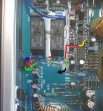
I will try and draw it out, but so far, pins 8 and 11 are connected and from pin 11 it goes through R5 to R8 (light blue with 1 dark blue band) to the collector of Q1.
(+) motor connector goes to R4 then R6 to Emitter of Q1.
(+) motor connector goes to R4 then R6 to Emitter of Q1.
Driver board for the audio outputs? H200306011.
There is no driver board per say for the power supply. All the components are on the main board. I can get a better picture of that area if necessary.
When I said Q1 in #82 I was referring to the KD600, not the internal driver transistor of the 494.
What type of resistor are the blue ones with one blue band? They don't appear to provide any appreciable resistance when checked with the dmm? I pretty sure I have seen them in an image in the tutorial, but can't find them again.
Last edited:
How much current does the amp draw when the fan is plugged in?
Does the fan turn when plugged in?
Does the fan turn when plugged in?
I placed my dmm in series with B+ set to amps and the amplifier idles at 1.7 amps.
As soon as the fan is plugged in it drops to 0.13 amps.
The fan tries to start for a fraction of a second.
As soon as the fan is plugged in it drops to 0.13 amps.
The fan tries to start for a fraction of a second.
Yes sir, assuming the fan is wired correctly internally. i.e. red wire from fan is to V+ on board.
I swapped them since you asked and it made no difference.
I swapped them since you asked and it made no difference.
I found one and there was no difference.
I checked the second fan before I tried it and it was pulling 100 mA at 12 Vdc, just to let you know.
I checked the second fan before I tried it and it was pulling 100 mA at 12 Vdc, just to let you know.
Did you say that there was a resistor in series with the collector of Q1?
I missed this earlier:
What type of resistor are the blue ones with one blue band? They don't appear to provide any appreciable resistance when checked with the dmm? I pretty sure I have seen them in an image in the tutorial, but can't find them again.
Blue band? A black band is the marking on a 0 ohm resistor. They are sometimes used as jumpers. In the Earthquake amps, they were used in the over-current protection circuit as shunt resistors.
What is the source of voltage for the collector of Q1?
What is the Zener diode connected to in that area?
What is the Zener diode connected to in that area?
I'm not sure. I thought the voltage was coming from pin 11 of the 494.
One side of ZD1 is connected to the capacitor next to it and the 470 ohm R7 and the base of Q1.
I am reading over the protection circuit pages in the tutorial and I will disassemble the amp tomorrow and also trace the circuit more completely.
Thank you
One side of ZD1 is connected to the capacitor next to it and the 470 ohm R7 and the base of Q1.
I am reading over the protection circuit pages in the tutorial and I will disassemble the amp tomorrow and also trace the circuit more completely.
Thank you
The collectors of the two outputs of the 494 and the collector of Q1 are being supplied by the same source.
Q1 appears to be a regulator.
Is the fan a 12v or a 5v fan?
Q1 appears to be a regulator.
Is the fan a 12v or a 5v fan?
Okay, I will try and do some tracing today and let you know.
I need to get a better understanding of how/which way the current flows from component to component. I seem to always be looking at backwards.
The fan is 12V.
I need to get a better understanding of how/which way the current flows from component to component. I seem to always be looking at backwards.
The fan is 12V.
Did you believe that the source of the voltage was pin 11 of the 494 or did you think that it was coming from that direction on the board?
Yes, my first thought was that the source of the voltage to the KD600 was pin 11 because it was labeled output. I figured that there was a source of input into the 494 and pin 11 and 8 were outputs as a result of that input, maybe Vcc? Maybe using a part of the 494 as a "regulator"? I am trying to learn, so I look at things and form hypotheses about what is going on, many times I am wrong, sometimes I get it right. It is obviously nice when I get it right, but I tend to learn more when I get it wrong at first.
After removing the board and following the traces on the bottom of the pcb, it was clear that pin 11 and 8 were sourced through a resistor in series connected to B+.
That resistor was labeled 2.2 ohms but read 888 ohms, which is were the voltage drop was occurring. I replaced the resistor with a new resistor marked 2.2 ohms now I am getting 12V to the input of the fan motor and everything is working properly.
I will put it all together and hopefully be done with this one. Although it has been very satisfying to get it working, with your help of course, I have been working on this one for a long time. It has been for the better as I have learned a lot, but I would hate to add up the hours and parts I have put into this, for what If I was lucky is a $50.00 amplifier.
Thank you for your help Perry. I could have not done it without your help and the tutorial.
If anybody is reading this and is interested in repairing or simply learning about how amplifiers/electronics works, buy the tutorial, it is worth every penny and then some.
- Home
- General Interest
- Car Audio
- Cadence M4000