Hi epa,
Nah, not 3 dB over the entire passband. That the overall output level is lower is probably also caused by the additional (electric) resistance that is absent in a linear model. If you don't have reliable impedance data you can always use the minimum impedance from the manufacturers datasheet to replace Re in model for an level and response correction. I was more referring to filling the big saddle in the middle (roughly 40hz to 70Hz) or perhaps I should say, more like your original model.
Hmm, no word from the man... that doesn't sound like oli at all.
Regards,
Djim
Last edited:
Just finished reading this entire thread... I didnt see much regarding the development of the custom S Baffle. It was mentioned early and again by Djim. I saw speculation from horn resp it would help with the upper frequencies. Was EPA/Crescendos FT-30 ever built with and without the S Baffle infront of the driver and compared?
I have some 18SW115's I'm debating on what to do with and this design looks like it hits my flat to 30 hzish goal. I did see that the group delay was pretty high at lower frequencies early in the thread. Was this fixed in the final design. I see Crescendo's very thorough testing, but am new to spectral decay graphs. Just curious about this designs "tightness or muddiness" of bass compared to others (I know that there is more to perceived sound than just group delay, thats why I'm going to keep building designs until I collect them all 😉 ). Also if anyone has a copy of the Solidworks model, I would love it.
Thanks
Hi treukauf,
A couple pages back, the group delay doesn’t look too bad to me. I don’t notice muddy-ness. Sounds pretty defined to us.
Do you have the 18SW115-4 or 18SW115-8?
Cheers,
Justin
A couple pages back, the group delay doesn’t look too bad to me. I don’t notice muddy-ness. Sounds pretty defined to us.
Do you have the 18SW115-4 or 18SW115-8?
Cheers,
Justin
Justin,
I have the 18SW115-4. Are the PDF drawings that Xo1C did back on page 73 still correct except for the baffle or have things changed? Also do you have any dimensions for the "curved section the driver fires into in the first section you came up with? I see a screenshot in post 773. Is that what you ended up building?
Thanks
C/E/X PA Flat to 30 (FT30) PA TH Awesomeness
Last edited:
Hi treukauf,
Ah, meant to touch on the S-baffle. It didn’t seem to be an improvement when I tested it in the enclosure you linked to. I had it loaded with the 18SW100-8. I then cut out the baffle to 3/4 open (as suggested by Djim) and then full open. The most output and smoothest response was with the baffle fully cut out during low power measurements. I did not take high power measurements at that time. I only ever built one prototype box of that design years ago. I’ve built four of the most recently posted design c/o epa. That’s the design I was commenting in regards to group delay in my previous post.
Cheers,
Justin.
Thanks for the info. I had missed epas link to the dwg files in 773. Im going to model this up in solidworks this week and hopefully cut wood soon. You guys went on quite a journey in this thread! Thanks for the hard work.
How many watts rms have you been pushing through these playing the good ol low crestfactor edm. I plan on running 2 with behringer nu6000s.
How many watts rms have you been pushing through these playing the good ol low crestfactor edm. I plan on running 2 with behringer nu6000s.
My peak limiter is set to engage at 91V and power limiter is set to keep VC temps down (outer magnet temps stay below 150*F).
Thanks epa.
Justin, I see you have your Low pass filter set to 70 hz (without eq) and 115hz (with eq, I assume db=hz haha) post #956. Is there a reason for the low 70 hz, like sound quality/ringing issues, or were you just trying to avoid the rising response of this design? Wasn't sure if you were trying to use your SS15's or something for upper bass.
Justin, I see you have your Low pass filter set to 70 hz (without eq) and 115hz (with eq, I assume db=hz haha) post #956. Is there a reason for the low 70 hz, like sound quality/ringing issues, or were you just trying to avoid the rising response of this design? Wasn't sure if you were trying to use your SS15's or something for upper bass.
treukauf,
And “Thought” should be “Though” - wow, a few typos there. Yes, 115dB should be 115Hz. And I believe the low LPF we previously used (before EQ) was set in the low to mid-70Hz, but we also used 63-66Hz BW18 LPF with decent results. There are some response peaks after 100Hz that lend a boxy sound if not EQ’d out or if crossed over too high w/o EQ.
And “Thought” should be “Though” - wow, a few typos there. Yes, 115dB should be 115Hz. And I believe the low LPF we previously used (before EQ) was set in the low to mid-70Hz, but we also used 63-66Hz BW18 LPF with decent results. There are some response peaks after 100Hz that lend a boxy sound if not EQ’d out or if crossed over too high w/o EQ.
Has anyone tried fitting a 21 inch woofer in this enclosure?
Just playing around with the idea of building this enclosure as its easier to build than the Othorn.
Just playing around with the idea of building this enclosure as its easier to build than the Othorn.
Has anyone tried fitting a 21 inch woofer in this enclosure?
Just playing around with the idea of building this enclosure as its easier to build than the Othorn.
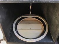
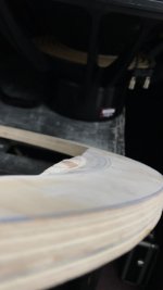
I started making a spacer ring a couple weeks ago to try just this. The original plan’s baffle is not deep enough — so, to prevent the driver frame from hanging out of the front of the cab, the spacer needs to be shifted off-center to the rear of the existing baffle and part of the 21” baffle cut-out ring needs to stay intact to prevent the driver from firing into the wrong part of the horn. The small part that stays intact needs to be routed/cut down to make clearance of the cone edge/surround under high drive levels. You can see some progress (I have more cutting to do) from two weeks ago (see attached). Also, my particular center brace needed quite a bit of modification to clear the bigger driver’s frame and magnet. I did not make my center brace from a cutsheet though, so you might have a different scenario.
it could be made to suit an 21"
Hi Erik! That might be pretty neat. The 21SW152 & 21DS115 sim similarly to the preferred 18” drivers, but allow much more input power before excursion is reached.
Ever hear anything from Oliver?
Cheers, all!
Attachments
Last edited:
hi justin
i don't know what happend to oliver,i'm sort of worried too.
the driver sims best is the 21DS115-4ohm for the FT30.
it has a litle bump on 60 hz of 1 db.
it wil need a slight change in the cone correction,and the speaker baffle
could point me to olivers sub youre reffering to?
to bad youre on the other side of the pond,where i could make the pannels on my router.
grt erik
Hello all,
Would Fane COLOSSUS 18XB drivers be suitable for these boxes? Considering building some from the CAD files Epa posted.
COLOSSUS 18XB
Best,
B
Would Fane COLOSSUS 18XB drivers be suitable for these boxes? Considering building some from the CAD files Epa posted.
COLOSSUS 18XB
Best,
B
downsizing is possible, yes... but two problems:
- the tangband doesn´t have optimal parameters for a design like this
- the length of the horn determines the lowest cut off frequency - and the tangband has such a small cone area, that you would end up with a very long, thin pipe... Other Tapped horn designs would be easier und better to build for smaller drivers like this.
look around for the hornresp data, put it into hornresp and use the downsize tool in hornresp to make a smaller version, then put the data of the tangband in it and see what happens 🙂
youre better of designing something from scratch imo
first thing is to put the data in hr and go from there
edit/ post 999,
first thing is to put the data in hr and go from there
edit/ post 999,
Last edited:
Post 1k !!!! Yeah, Sub design is not linear, you can't scale down measurements and just stick a small driver in it. I guess we break laws of Physics that way.youre better of designing something from scratch imo
first thing is to put the data in hr and go from there
edit/ post 999,

- Home
- Loudspeakers
- Subwoofers
- C/E/X PA Flat to 30 (FT30) PA TH Awesomeness