Ed:
It looks like the ringing has at least 10 cycles within a roughly 1 uSec timeframe. That would make the ringing approximately 10 Mhz. If you are saying that you have a slight lowering of this 10Mhz content, then you are indeed working in the RF range. Not an easy thing to do accurately.
What L would be required to give this result at 10Mhz?
Can you explain what the pic is showing? It says a peak to peak in the 11 volt range, with a 2 uSec period.. The time scale is 5 uSec and the vert scale is 5 mV, so I could use a little help with the explanation. Thanks.
Cheers, John
John,
You are right on the spike clipper some information is lost. If the spike were not clipped the following circuits may clip or saturate and the result is even worse. So I think we are in agreement.
The issue of requiring Maxwell's Demon or equivalent is moot, because we do have some information about the noise that is out of band and can safely reduce that (Yes band edges will reduce some information) and clipping the spikes also reduces noise again with another loss of information. But the final result is an improvement in performance of the system following the Demon or equal.
As to the rest of the questions, I may have more about the device in question tomorrow, as the folks who consider some of the information a trade secret have been following this thread and may let the construction details be shown.
The required L would be 15uh. The top peak to the bottom of the peak I assume on the entire trace is 11mV.
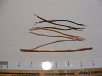
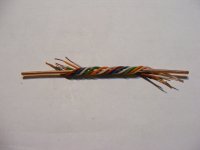
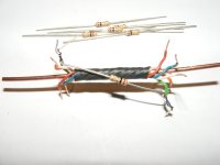
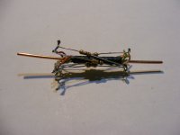
Now the starting point 7 wires 1 14 gauge the other 6 cat5 scraps. Wrap the six small wires two or three turns around the uninsulated thicker one. Note the direction of wind. Be sure they do not cross over each other. Secure them with a piece of 1/4" diameter heatshrink.
Attachments
Last edited:
Now why does this attenuate high frequency noise? What is the impedance at the frequencies we wish to pass unaltered? (Rhetorical questions no need to answer.)
Now why does this attenuate high frequency noise? What is the impedance at the frequencies we wish to pass unaltered? (Rhetorical questions no need to answer.)
Imagine the magnetic field that is generated by current within the 14 guage wire. Use the right hand rule.
Now, think of the wrapped wires as having a common centroid with the 14 guage wire.
The resistor completes a conductive loop which traps magnetic field.
Now, think about the current that can flow within the loop. It couples to the primary, it's voltage is proportional to the rate of change of the magnetic field caused by the current.
So what is it? The resistor sees current proportional to the rate of change of the field, so dissipation is hi-pass.
You've made a hi-pass filter. A convoluted one, but one nonetheless. And this hi-pass filter couples to a dissipative element. So, the overall effect is one of hi frequency attenuation.
Neat..
Boost the frequency up two orders of magnitude, change the wiring a tad, and voila...a directional coupler. I learned about those widgits back in '74.
Cheers, John
Please don't play dumb with me, SY. The answer is: 'We invented it!' How often I have heard these 3 phrases over the decades? '-)
SY, you and I have not 'communicated' for a long time, and I will leave it to others to explain it. It wasn't directed AT you in the first place.
and the relevance of all this to listening in a quiet room @ maybe 50dB noise floor to typical sources with magnitudes higher distortion levels is.... what???
irrelevance...but don't let the real world stop you in fantasy land... heheh
irrelevance...but don't let the real world stop you in fantasy land... heheh
interesting experiment, but... what's the relevance?
To the thread topic? Nothing. Interesting demonstration of an alternate way to build a low pass filter, but no relationship to the repackaged resistor.
The dissipative element is the 6 x 1 ohm resistors.You've made a hi-pass filter. A convoluted one, but one nonetheless. And this hi-pass filter couples to a dissipative element. So, the overall effect is one of hi frequency attenuation.
The QP outer sleeve measures 15 ohms end to end (according to a post somewhere).
Does the QP constitute a resistive load at high frequencies ?.
I thought so, but it had me lost when it headed gigahz
Yeah, we've moved on from "does it do anything at audio" to "can't we find something else it does?" That's pretty pitiful, IMO.
It is a 'concept' design that shows that you cannot ALWAYS trust your previous experience and dismiss something, just because you cannot understand how it could possibly work.
SY we have taken apart your measurements, and found them wanting.
SY we have taken apart your measurements, and found them wanting.
SY we have taken apart your measurements, and found them wanting.
You've done nothing of the kind. Quite the contrary- the measurements of someone else that you cited (you've contributed nothing of your own) agreed exactly with what I saw: it's a resistor.
- Status
- Not open for further replies.
- Home
- General Interest
- Everything Else
- Bybee Quantum Purifier Measurement and Analysis