dear zen mod
think I found the problem. I use this power supply
and there are to outputs from my torrodial +25 -25 and I connected them both..1 on the left side and one on the right side. removed one of them ten volt is 25....
so guess i need to go for single rail ??
so ...what do you think?
2. think i blow up something?? no smoke or exessive heat...
Attachments

Last edited:
I think that this is pic of article on which FW is used without permission
further - my crystal ball is muddy these days , so I can't imagine how you populate and connected that bare pcb from pic
hold your horses ; you're playing with some money , serious amount of energy and - most important - mains voltage ;
so - lack of knowledge and experience you must compensate with careful planning and thinking ;
I said - post pictures of your work , so we can see and comment
search forum for bulb tester ; convenient tool for novices
pics tomorrow morning
and thank you for helping me out.
already scrapped a china set from this guy do to copyrighs, so i toght i've would at least save thes boards since they are already populated with kendeil and what not.. wallet will probly die if i have to scrap them 2... 🙁
pics comming soon. thanks
and thank you for helping me out.
already scrapped a china set from this guy do to copyrighs, so i toght i've would at least save thes boards since they are already populated with kendeil and what not.. wallet will probly die if i have to scrap them 2... 🙁
pics comming soon. thanks
power supply
hello.
input torrodial 230v blue brown. sec1 black red 18v. sec2 orange red 18v
So after meassurement this is what i have:
output rectifier 1: 16,6 vdc
output rectifier 2: 16,7 vdc
so question is : how do i connect this ? se 3 post earlier for cond bank that i use. ( have 2 of them) but really wanted to use only one.
pics of amp to come in a few hours 🙂
ps. Zen Mod: the letters of FW onboard will immediatly be removed. I bought this item before I knew of this "copyright" violation. So when I was told I made a donation to pay for my sins 🙂
Last edited:
I'm waiting for pics 😉
DC voltage is too low ; is it measured with just diode bridges , without caps mounted on-board ?
DC voltage is too low ; is it measured with just diode bridges , without caps mounted on-board ?
I'm waiting for pics 😉
DC voltage is too low ; is it measured with just diode bridges , without caps mounted on-board ?
yes probes directly to diodebridge without caps con.
of to town to buy new camera.... old one is broken apperantly
of to town to buy new camera....
That's great idea, 😀😀
Seem your DC voltage to low like ZM said,
with input bridge 18 V (AC), output must approximately 25 VDC from (18 x 1.41).
pics
so here some pics. if I could only get them uploaded!!!!! seems there is a problem with uploading now...
when only 1sec is con. I get 25vdc on the powerboard. problem is when I con. the 2sec from torrodial then I get 50v. so.... what to do? think I read somwhere a while ago that there should be a way to con 2 secondaries... thank you all for any help.
https://www.facebook.com/media/set/?set=a.323986057632143.84441.100000622533370&type=1
only place I could upload the pics
Last edited:

I don't have FB account ....... and I really don't need it
So...you tried to follow the link and no pics?
know where i can upload?
thank you for your patience.
trying again
http://dl.dropbox.com/u/57077275/downside.jpg
http://dl.dropbox.com/u/57077275/upside.jpg
http://dl.dropbox.com/u/57077275/004.JPG
http://dl.dropbox.com/u/57077275/005.JPG
http://dl.dropbox.com/u/57077275/006.JPG
http://dl.dropbox.com/u/57077275/007.JPG
http://dl.dropbox.com/u/57077275/008.JPG
http://dl.dropbox.com/u/57077275/003.JPG
lets hope this works
thank you zen master
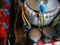
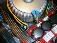
the or/yel are not twisted on their route to the rectifier.
I wonder if the red/blk are similarly untwisted?
I wonder if the red/blk are similarly untwisted?
oiphy
now I see that you resize them nicely , so you can directly upload them here
reply-manage attachments etc , same as with first pic you attached here
you can use DB for larger ones
edit : ups - just first one is adequate in size for attaching here 😉
now I see that you resize them nicely , so you can directly upload them here
reply-manage attachments etc , same as with first pic you attached here
you can use DB for larger ones
edit : ups - just first one is adequate in size for attaching here 😉
Last edited:
heyyyy
why cant I do that...???
oh wait .... only get that file is to big....
ARGHHHHH..
http://dl.dropbox.com/u/57077275/overview 001.JPG
why cant I do that...???
oh wait .... only get that file is to big....
ARGHHHHH..
http://dl.dropbox.com/u/57077275/overview 001.JPG
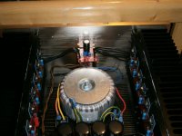
for now they'r not twisted. but the problem is getting it up and running, or should I say them (have 2 monoblocks)
for now Im getting 50 vdc to psu when 2 sec is connected... look at pics.. see I disconnected one sec. and then I have 25v soooooooo whats wrong ??
for now Im getting 50 vdc to psu when 2 sec is connected... look at pics.. see I disconnected one sec. and then I have 25v soooooooo whats wrong ??
the or/yel are not twisted on their route to the rectifier.
I wonder if the red/blk are similarly untwisted?
first - search for "bulb tester" ( AndrewT is strong proponnt of that tool , with reason) ;
make one
connect amp via BT (say that 40-60W is good for start)
disconnect amp pcbs from PSU and test just PSU
from pics I see that you connected Graetzs as needed - check polarity 3 times before powering up!
power up and measure voltage on each output
BT will lit brightly and dim after sec-2 if everything is OK
if BT is bright for prolonged time , something is wrong
measure voltage between each + and gnd - you can expect DC voltage in range Vac x 1.41
measure voltage between each - and gnd - same voltage ( opposite polarity , off course)
example - for 18Vac secondaries , you can expect 18x1,41~25Vdc
when you are done with that , report here
but first !! write what wire colors are written on xformer - we need to check did you connected secondaries as needed
Last edited:
- Home
- Amplifiers
- Pass Labs
- Burning Amplifier BA-2